
Agricultural Tool Laser Cladding for Wear Resistance and Service Life Extension
Application Overview
Agricultural cutting and soil-engaging tools operate under continuous abrasive wear, impact, soil friction, sand, and hard-particle erosion.
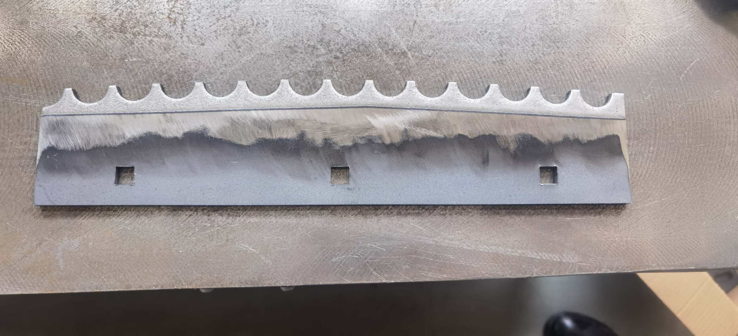
In this application, an agricultural wear component showed rapid material loss along the working edge and contact surface after repeated service. The objective was not only to restore the damaged region, but also to improve wear resistance so that the repaired tool could maintain its geometry for a longer operating period.
Laser cladding was selected because it allowed a wear-resistant alloy layer to be deposited only on the high-wear region while limiting unnecessary thermal influence on the rest of the component.
Workpiece and Operating Conditions
Component: Agricultural cutting / soil-engaging tool
Base Material: Medium-carbon or low-alloy steel
Typical Workpiece Size: Small-to-medium agricultural wear component
Main Wear Area: Cutting edge and soil-contact surface
Operating Environment: Soil, sand, stone particles and repeated mechanical impact
Primary Failure Mode: Abrasive wear combined with localized impact wear
Exact customer dimensions and workpiece geometry are not disclosed for confidentiality reasons.
Failure Mechanism
The working surface was continuously exposed to soil and hard mineral particles.
The main degradation mechanisms included:
- Abrasive wear
- Edge rounding
- Local material loss
- Surface grooving
- Repeated impact
- Progressive reduction of effective cutting geometry
As the working edge wore, cutting efficiency decreased and the component required more frequent replacement or maintenance.
The engineering requirement was therefore:
Restore the worn area + Improve surface wear resistance + Maintain sufficient toughness
Simply maximizing coating hardness was not considered appropriate because agricultural tools can also experience impact and shock loading.
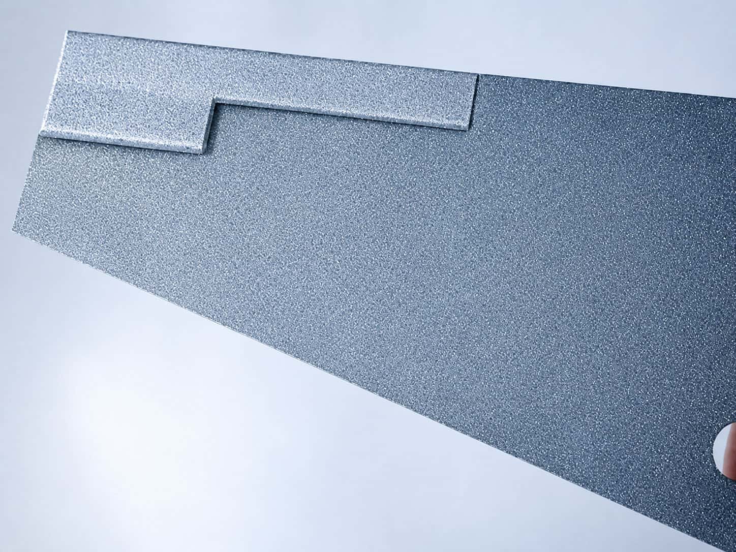
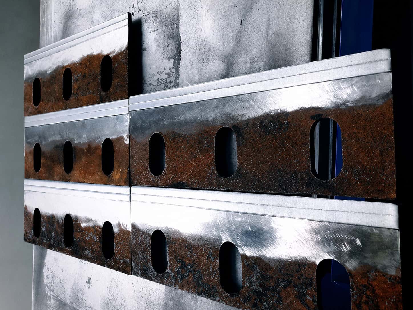
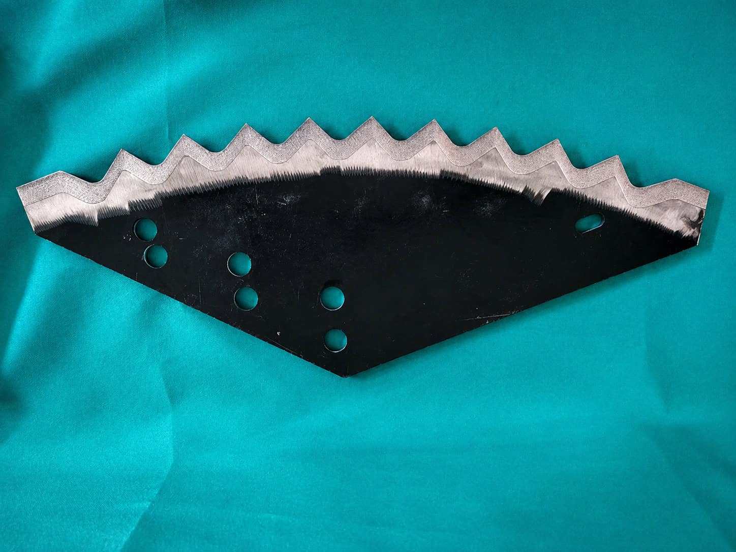
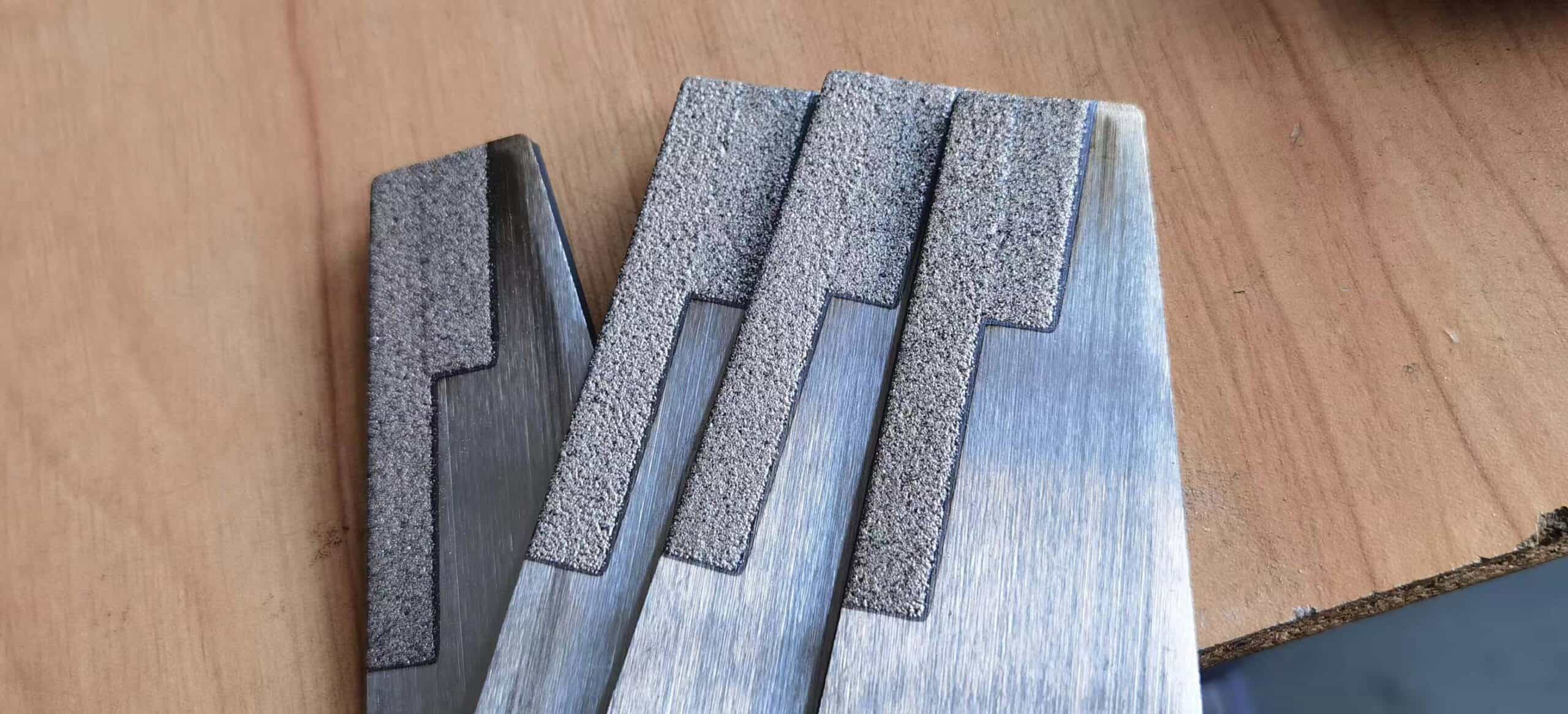
Repair and Surface Engineering Objective
The laser cladding process was designed to achieve several objectives:
- Rebuild the worn functional area
- Improve abrasive wear resistance
- Maintain reliable metallurgical bonding
- Limit thermal distortion
- Preserve the strength of the base component
- Leave suitable allowance for final finishing where required
The coating needed to be hard enough to resist soil abrasion while retaining sufficient toughness for practical field use.
Why Laser Cladding Was Selected
Laser cladding was selected because this application required more than a thin surface coating.
The process offered:
- Metallurgical bonding
- Controlled material buildup
- Localized processing
- Low dilution
- Limited heat-affected area
- Flexible wear-resistant alloy selection
- Good compatibility with automated batch processing
Compared with replacing the entire component with a more expensive bulk alloy, laser cladding allowed high-performance material to be applied only where it was needed.
Material Strategy
A wear-resistant metallic alloy system was selected according to the actual wear mechanism.
For agricultural tooling, suitable material strategies may include:
- Iron-based wear-resistant alloys
- Nickel-based wear-resistant alloys
- Carbide-reinforced metal matrix systems
- Other application-specific hardfacing powders
Where severe abrasive wear is present, hard carbide reinforcement can be introduced into a metallic matrix.
However, the carbide fraction must be controlled carefully because excessive hardness or brittle-phase content can increase cracking or impact sensitivity.
The final powder composition should therefore balance:
Hardness + Toughness + Metallurgical Compatibility + Cost
Laser Cladding Process
Before cladding, the worn area was cleaned and prepared to remove damaged or contaminated surface material.
The general process route was:
Surface Preparation → Workpiece Positioning → Laser Cladding → Multi-Track Overlap → Cooling → Inspection → Final Finishing if Required
For the wear surface, the cladding tracks were arranged according to the geometry of the cutting edge and contact region.
The objective was to maintain stable track overlap and avoid excessive heat accumulation in the relatively compact workpiece.
Representative Process Window
The following values are representative of similar agricultural-tool laser cladding applications and are not the confidential parameters of a specific customer project.
| Parameter | Representative Range |
|---|---|
| Laser Power | Approx. 2–4 kW |
| Deposition Method | Powder-fed laser cladding |
| Typical Layer Thickness | Approx. 0.5–1.5 mm per layer |
| Processing Mode | Single or multi-layer overlapping tracks |
| Powder System | Wear-resistant alloy / carbide-reinforced alloy |
| Shielding | Inert gas protection |
| Motion | CNC or robotic programmed path |
| Final Processing | Grinding or machining where required |
Actual parameters depend on workpiece thickness, substrate chemistry, powder composition, desired hardness, and coating geometry.
Recommended Equipment Architecture
For similar agricultural wear components, a suitable automated system may include:
For relatively simple and repetitive tools, a compact CNC cladding system may provide better economics.
For multiple component geometries or more complex wear surfaces, an industrial robot can provide greater flexibility.
A typical system may include:
- 2–4 kW industrial fiber laser
- Powder-fed laser cladding head
- Single- or dual-hopper powder feeder
- CNC or robotic motion system
- Customized agricultural-tool fixture
- Industrial chiller
- Shielding gas system
- Integrated process control
The equipment configuration should be selected according to production volume and workpiece variety.
Processing Result
The worn functional area was rebuilt with a dense metallurgically bonded deposited layer.
The repaired component achieved:
- Restored working geometry
- Improved wear-resistant surface
- Controlled cladding thickness
- Limited thermal influence on the surrounding substrate
- Suitable surface condition for final finishing
For applications of this type, the primary engineering benefit is the ability to apply a higher-performance material only to the critical wear region instead of replacing the complete component or manufacturing it entirely from an expensive wear-resistant alloy.
Engineering Notes for Similar Agricultural Components
Laser cladding can be considered for agricultural components such as:
- Cutting blades
- Tillage tools
- Soil-engaging tools
- Rotary tiller blades
- Wear edges
- Agricultural knives
- Harvesting components
- Other high-wear working surfaces
However, process design should always consider both wear and impact.
A coating with extremely high hardness is not automatically the best solution.
For agricultural machinery, the correct coating should balance:
Abrasive Wear Resistance + Impact Resistance + Crack Resistance + Cost
For high-volume low-cost consumable tools, PTA or conventional hardfacing may sometimes provide better economics.
Laser cladding becomes especially attractive when:
- Component value is higher
- Cladding position must be precise
- Heat input must be controlled
- Wear-resistant material usage should be minimized
- Automated repeatability is important
- Surface performance must be improved beyond conventional repair
Confidentiality Notice
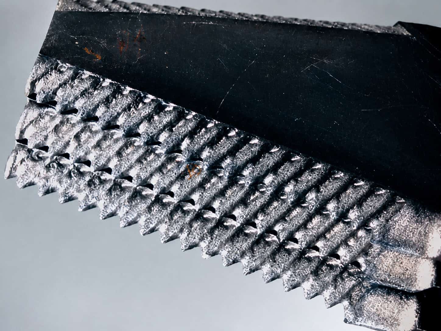
This application case is based on an actual industrial laser cladding project. Customer identity, exact workpiece dimensions, proprietary process parameters and original customer images have been withheld or generalized to protect confidentiality. Representative workpiece images may be used for technical illustration.
Have a Similar Agricultural Wear Component?
Send us your workpiece drawing, base material, dimensions, worn area, operating conditions and required surface properties.
Our engineering team can evaluate the laser cladding process, recommend a suitable coating material, and develop an appropriate equipment configuration for the application.
