
Automotive Component Laser Cladding: Brake Discs, Valves and Powertrain Component Remanufacturing
Application Overview
Automotive components operate under very different combinations of friction, wear, corrosion, cyclic loading, and elevated temperatures. Depending on the component, laser cladding can be used either to create a functional wear-resistant surface on a new part or to restore material lost from a worn high-value component.
This application case summarizes industrial laser cladding experience involving representative automotive components including:
- Brake discs
- Engine valves and valve seats
- Crankshafts
- Selected engine and powertrain wear components
Although these components require different materials and processing strategies, they share a common engineering objective:
Apply high-performance material only to the critical functional surface while controlling dilution, heat input and dimensional change.
1. Automotive Brake Disc Laser Cladding
Application Background
Brake discs operate under repeated friction, thermal cycling, and mechanical loading.
During braking, friction between the brake pad and disc gradually removes material from the working surface. The resulting wear not only affects component life but also contributes to particulate emissions.
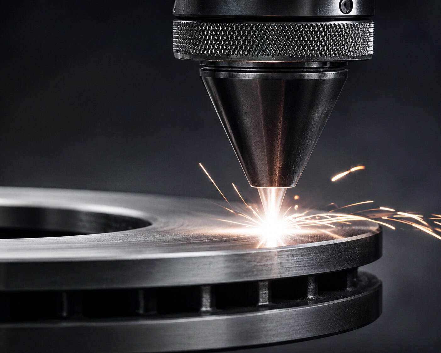
For suitable brake disc applications, laser cladding can be used to produce a functional surface layer with improved wear and corrosion resistance.
The objective is generally not to rebuild a severely damaged brake disc, but to engineer a more durable friction surface.
Workpiece and Operating Conditions
Component: Automotive brake disc
Base material: Typically cast iron or application-specific brake disc material
Processing area: Annular friction surface
Primary conditions: Friction, wear, thermal cycling and environmental corrosion
Processing mode: Continuous circumferential surface deposition
Exact customer dimensions and proprietary coating specifications are withheld for confidentiality.
Engineering Challenge
Brake disc laser cladding requires considerably more than simply depositing a hard coating.
The deposited layer must be compatible with:
- Repeated braking cycles
- Frictional heating
- Thermal expansion
- Substrate metallurgy
- Surface finishing requirements
- Friction-pair performance
At the same time, excessive dilution or heat accumulation should be avoided.
For production applications, deposition efficiency and coating uniformity across the complete annular surface are also important.
Why Laser Cladding Was Selected
Laser cladding provides several advantages for brake disc surface engineering:
- Metallurgical bonding
- Controlled coating thickness
- Low dilution
- Localized thermal input
- High processing repeatability
- Automated circumferential processing
- Flexible coating material design
For high-volume production, high-speed laser cladding strategies can also be evaluated to increase surface coverage efficiency while maintaining a relatively thin functional layer.
Material Strategy
The coating system should be selected according to the brake disc substrate, friction requirements, wear mechanism, corrosion environment, and subsequent finishing process.
Potential material strategies include:
- Iron-based wear-resistant systems
- Nickel-based functional alloy systems
- Carbide-reinforced metallic coatings
- Application-specific composite coating systems
The objective is not simply to maximize hardness.
The complete coating must balance:
Wear Resistance + Friction Performance + Thermal Stability + Crack Resistance + Substrate Compatibility
Final material selection requires process and friction-performance validation.
Representative Process Window
| Parameter | Representative Range / Strategy |
|---|---|
| Process | Powder-fed laser cladding |
| Laser Power | Application-dependent, typically multi-kW |
| Coating Strategy | Thin functional surface deposition |
| Processing Path | Circumferential overlapping tracks |
| Material | Wear-resistant metallic/composite system |
| Motion | High-speed rotary motion + synchronized linear movement |
| Shielding | Inert gas |
| Post-Processing | Grinding / finishing as required |
These values represent a general engineering window rather than confidential parameters from a specific customer project.
2. Engine Valve and Valve Seat Laser Cladding
Application Background
Engine valves and valve seats operate under repeated mechanical contact and elevated-temperature conditions.
Depending on engine design and service environment, functional surfaces can experience:
- Adhesive wear
- Impact wear
- Thermal cycling
- Oxidation
- Corrosive combustion products
- Surface recession
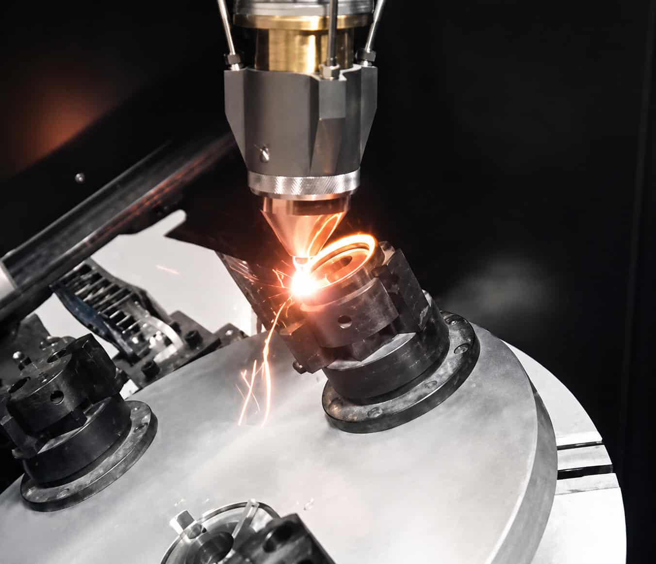
Laser cladding can be used to deposit a high-performance alloy onto selected valve or valve-seat contact surfaces.
Engineering Objective
The objective is to improve the functional surface without manufacturing the entire component from an expensive high-performance alloy.
Typical requirements include:
- High-temperature wear resistance
- Corrosion and oxidation resistance
- Reliable metallurgical bonding
- Controlled deposition geometry
- Limited thermal influence on the component
- Machinability after deposition
Because the functional area is relatively small, localized laser deposition provides an efficient material-use strategy.
Material Strategy
Depending on service conditions, suitable coating systems may include:
- Cobalt-based wear-resistant alloys
- Nickel-based high-temperature alloys
- Iron-based functional alloys
- Other application-specific materials
The material must be selected according to actual operating temperature, contact stress, substrate composition, and required surface properties.
Laser Cladding Process
A representative process route is:
Surface Preparation → Component Positioning → Localized Laser Cladding → Controlled Cooling → Inspection → Precision Finishing
For rotationally symmetrical valve components, synchronized rotary motion can provide consistent deposition around the functional surface.
For more complex geometries, CNC or robotic motion can be used.
3. Crankshaft Laser Cladding Repair
Application Background
Crankshafts can develop localized wear on journals and other functional surfaces after prolonged operation.
Where the main crankshaft structure remains serviceable, replacing the entire component may not always be the most economical solution.
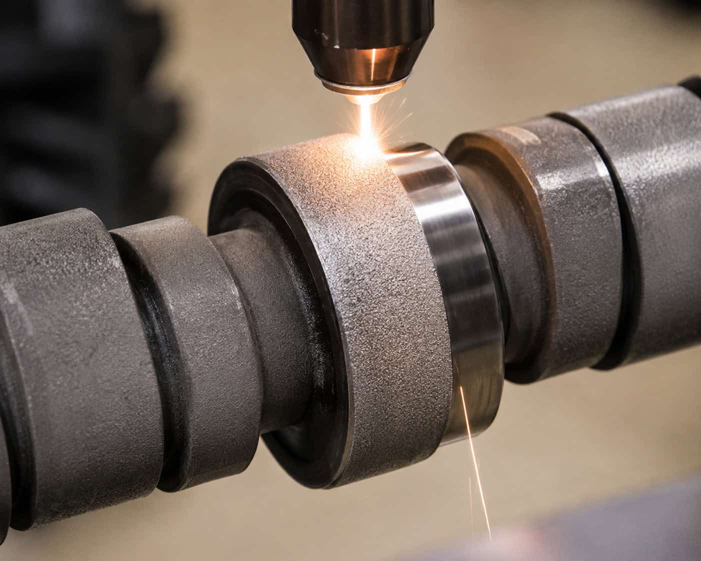
Laser cladding can provide a localized remanufacturing route.
The basic objective is:
Remove Damaged Surface → Rebuild Worn Region → Restore Machining Allowance → Finish to Required Dimensions
Failure Mechanism
Typical crankshaft surface damage can include:
- Journal wear
- Scoring
- Localized dimensional loss
- Surface fatigue damage
- Corrosion-assisted wear
Before repair, the component should be inspected to determine whether the damage is limited to a repairable surface region.
Laser cladding should not be treated as a solution for every damaged crankshaft. Components with unacceptable structural cracking or severe bulk damage require separate engineering assessment.
Why Laser Cladding Was Selected
For suitable repairable surfaces, laser cladding provides:
- Localized material deposition
- Metallurgical bonding
- Controlled dimensional buildup
- Limited heat input
- Relatively low distortion
- Machining allowance for final grinding
- Possibility of improving surface properties
This is particularly important for high-value shafts where maintaining geometric accuracy is critical.
Representative Process Strategy
A typical repair sequence may include:
Inspection → Removal of Damaged Material → Pre-Machining → Laser Cladding → Inspection → Precision Machining / Grinding
A rotary system synchronizes workpiece rotation with axial movement of the laser cladding head.
Depending on the component and repair objective, the deposited material can be selected to restore the original functional characteristics or provide improved wear performance.
4. Other Engine and Powertrain Components
Laser cladding can also be evaluated for selected automotive and powertrain components where localized wear, corrosion, or dimensional loss occurs.
Potential applications include:
- Shaft journals
- Bearing positions
- Transmission components
- Selected piston-related wear surfaces
- Rotational wear components
- Localized engine-component repair
However, not every automotive component is economically suitable for laser remanufacturing.
For inexpensive mass-produced components, direct replacement may remain more economical.
Laser cladding becomes particularly valuable when:
- The component has relatively high value
- Only a localized region has failed
- Replacement is expensive or time-consuming
- Dimensional restoration is required
- Improved surface properties provide additional value
5. Representative Automotive Laser Cladding System Architecture
Because brake discs, valves, and crankshafts have very different geometries, they should not be processed using a single fixed machine architecture.
A representative system can be configured from:
Industrial Fiber Laser + Laser Cladding Head + Powder Feeder + CNC/Robot + Rotary Positioner + Fixture + Process Control
For Brake Discs
A typical architecture may use:
Laser + Powder Feeder + Cladding Head + High-Speed Rotary Axis + Linear Motion
The focus is on efficient and uniform surface coverage.
For Valves and Valve Seats
A compact multi-axis or rotary processing platform can provide precise localized deposition.
For Crankshafts and Long Shafts
A suitable architecture may include:
Laser + Powder Feeder + Rotary Positioner + Long-Travel Linear Axis + Synchronized Motion Control
The final equipment configuration should therefore follow the workpiece rather than forcing different components into the same machine structure.
6. Key Process Parameters
Automotive laser cladding quality depends on the interaction of multiple parameters:
- Laser power
- Beam profile
- Spot size
- Powder feed rate
- Powder composition
- Travel speed
- Rotation speed
- Track overlap
- Layer thickness
- Shielding conditions
- Substrate temperature
- Cooling behavior
The appropriate parameter window differs substantially between a thin brake-disc functional coating and millimeter-scale crankshaft dimensional restoration.
For this reason, laser power alone cannot determine whether a system is suitable for an automotive application.
The complete:
Material + Laser + Powder + Motion + Thermal Process Window
must be developed around the component.
7. Processing Results
Across these automotive applications, laser cladding provides two different types of engineering value.
Surface Enhancement
For components such as brake discs and selected valve surfaces:
Base Component → Functional Laser-Clad Surface → Improved Surface Performance
Repair and Remanufacturing
For worn shafts and other high-value components:
Worn Component → Localized Material Restoration → Final Machining → Return to Required Geometry
This distinction is important.
Laser cladding is not only a repair technology, and it is not only a coating technology. Depending on the component, it can support both surface engineering and industrial remanufacturing.
8. Why Laser Cladding for Automotive Components?
Laser cladding is particularly attractive when the application requires a combination of:
- Metallurgical bonding
- Controlled dilution
- Localized processing
- Functional alloy deposition
- Dimensional restoration
- Limited thermal distortion
- Automated repeatability
However, it should not automatically replace conventional automotive manufacturing processes.
The correct technology depends on:
Component Value + Failure Mechanism + Material + Geometry + Production Volume + Required Surface Performance + Total Cost
For some components, conventional replacement or another coating process may remain more economical.
For others, laser cladding can provide a technically and economically attractive route to improved surface performance or component remanufacturing.
9. Recommended Equipment for Similar Applications
GREENSTONE can configure laser cladding systems according to different automotive component geometries and production requirements.
Representative configurations may include:
- CNC laser cladding systems
- Multi-axis laser processing systems
- Robotic laser cladding cells
- High-speed rotary cladding platforms
- Long-shaft laser remanufacturing systems
- Customized automated production cells
The system can integrate:
Laser Source + Cladding Head + Powder Feeder + Motion System + Positioner + Fixture + Process Monitoring + Safety Enclosure
For production applications, automation architecture, loading strategy, cycle time, and process repeatability should be evaluated together with the laser cladding process itself.
10. Engineering Notes for Similar Automotive Projects
Before developing a laser cladding solution, the following information should be confirmed:
- Workpiece drawing
- Base material
- Component dimensions
- Existing surface condition
- Wear or failure mechanism
- Required coating area
- Required coating thickness
- Required hardness or functional properties
- Post-machining requirements
- Target production volume
For repair projects, the remaining structural integrity of the component must also be evaluated.
For new-component surface enhancement, coating design should be validated against actual operating conditions.
Confidentiality Notice
This application case is based on actual industrial laser cladding applications. Customer identities, exact workpiece dimensions, proprietary material formulations, process parameters and original customer project information have been withheld or generalized to protect confidentiality. Representative images may be used for technical illustration and may not depict the original customer components.
Have a Similar Automotive Component?
Whether the requirement involves a brake disc functional coating, valve or valve-seat surface enhancement, crankshaft repair, or another automotive wear component, the appropriate solution should begin with the actual workpiece.
Send us your workpiece drawings, base material, dimensions, damaged or processing area, operating conditions, required surface properties and production target. Our engineering team can evaluate the laser cladding process, coating strategy and appropriate equipment configuration for your application.
