
Laser Cladding Repair of a High-Wear Forming Die: An Industrial Remanufacturing Case
Industrial forming dies are exposed to repeated mechanical loading, friction, impact, and localized surface wear. Once a critical forming area becomes worn, dimensional accuracy deteriorates and the die may no longer produce parts within the required tolerance.
Replacing the complete die is not always necessary. For components with sufficient remaining structural integrity, laser cladding repair can rebuild worn areas by depositing new metallic material onto the damaged surface, followed by machining to restore the original geometry.
In this industrial application, GREENSTONE used a powder-fed laser cladding process to rebuild the severely worn working areas of a forming die. The project covered damage assessment, machining preparation, cladding parameter programming, multi-track deposition, rotary and planar laser processing, and final machining. The completed components demonstrate how laser cladding can be integrated into a practical die remanufacturing workflow.
The Repair Challenge
The damaged tooling contained several curved and recessed working surfaces. Localized wear was concentrated around the forming regions where repeated contact had progressively removed material.
The repair therefore required more than simply applying a protective coating. Material had to be deposited with sufficient volume to rebuild the missing geometry so that the component could subsequently be machined back to its required dimensions.
This distinction is important:
Laser coating primarily modifies surface properties.
Laser cladding repair can combine surface modification with dimensional restoration by rebuilding worn material.
For this project, GREENSTONE used the second approach.
Initial Inspection of the Worn Die
Before laser processing, the worn components were inspected to determine the location and extent of material loss.
The damage was concentrated on functional surfaces with both curved and relatively flat geometries. Because these regions directly influence the shape and dimensional accuracy of the formed product, uncontrolled material loss could not simply be polished away.
The repair strategy therefore had to account for:
- the remaining substrate condition;
- the geometry of the worn area;
- accessibility of the laser cladding head;
- required material build-up;
- subsequent machining allowance;
- continuity between deposited tracks;
- final dimensional restoration.
Only after these factors were evaluated could the cladding path and processing sequence be established.
GREENSTONE Laser Cladding System
The repair was carried out using a GREENSTONE powder-fed laser cladding system configured for industrial component restoration.
The complete processing arrangement integrated the laser source, powder feeding system, laser cladding head, motion platform, rotary positioning capability, cooling system, and CNC/control system.
This type of integrated configuration is important for repair applications because the component may require several different motion strategies within the same project.
Flat or elongated surfaces can be processed using coordinated linear movement, while circumferential or rotationally symmetric areas can be cladded by synchronizing laser-head movement with workpiece rotation.
Why Powder-Fed Laser Cladding Was Used
Powder-fed laser cladding is particularly suitable for localized repair because deposition can be restricted to the areas where material is actually required.
During processing, metallic powder is delivered continuously into the laser interaction zone. The laser creates a controlled molten pool on the substrate and melts the incoming powder. After rapid solidification, a metallurgically bonded deposited track is formed.
Adjacent tracks are then overlapped to rebuild a larger area.
For this die repair, the deposition process had to provide both adequate bonding and sufficient build height for subsequent finish machining.
Repair Preparation
The damaged areas were prepared before deposition.
For a remanufacturing project, preparation has two main objectives. The first is to remove unsuitable surface material and expose a stable substrate. The second is to create a geometry that can be processed consistently by the laser cladding system.
The actual repair area was therefore defined before the cladding program was generated.
This is particularly important for severely worn dies. Attempting to deposit directly onto an irregular damaged profile without adequate preparation can make track height, overlap, stand-off distance, and final machining allowance more difficult to control.
CNC Programming and Motion Planning
The laser cladding trajectory was programmed through the system control platform before deposition.
For large repair areas, a single laser track is insufficient. The controller must coordinate a sequence of adjacent tracks so that the deposited material covers the complete damaged region.
The basic strategy was:
Define repair area → establish processing coordinates → program cladding path → set laser and motion parameters → verify movement → execute deposition
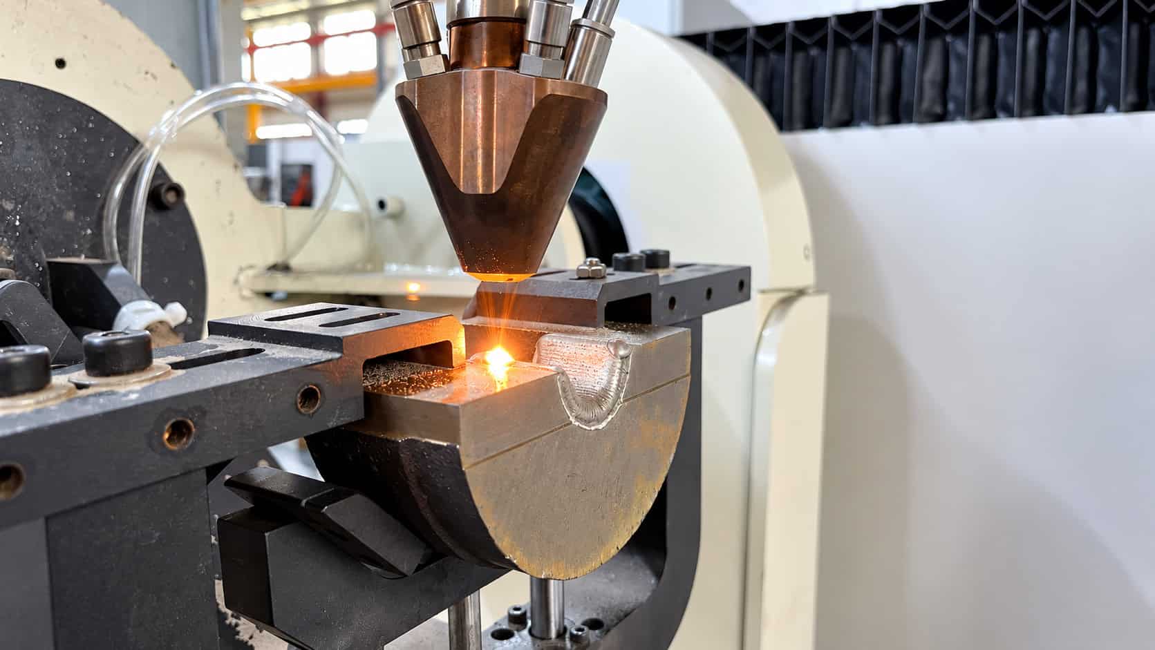
For curved and rotational features, the workpiece was mounted on a rotary fixture so that the laser cladding head could maintain an appropriate processing relationship with the surface while the component rotated.
Multi-Track Laser Cladding of Flat and Curved Areas
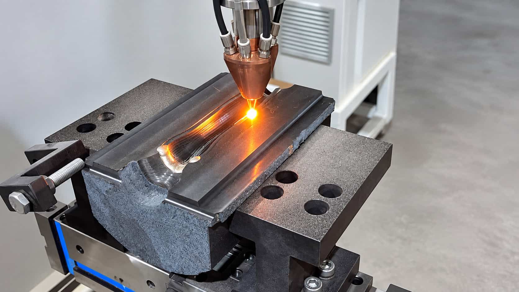
The repair involved repeated parallel and overlapping laser cladding tracks.
Each track formed a narrow deposited bead. Subsequent tracks were positioned beside the previous track with controlled overlap until the complete repair region had been rebuilt.
Track overlap is important because insufficient overlap can leave valleys between adjacent beads, while inappropriate energy input can create excessive remelting or an uneven deposited surface.
The deposited surface does not need to reproduce the final machined geometry immediately. For a repair project such as this, the more important objective is to create a continuous and sufficiently dense deposited layer with enough machining allowance for the finishing stage.
Laser Cladding of Recessed Forming Surfaces
Some of the worn regions were located inside recessed die features.
These areas require careful positioning of the cladding head because accessibility is more limited than on a simple flat surface.
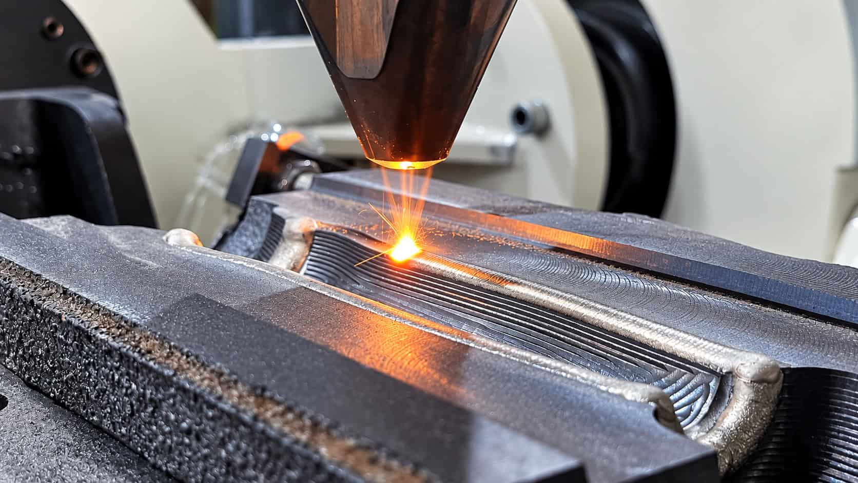
During deposition, the laser head followed the repair region while maintaining the required relationship between the laser spot, powder stream, and substrate.
Multiple overlapping tracks progressively filled the worn region.
The resulting as-cladded surface showed the characteristic parallel bead pattern of multi-track laser deposition. This surface was intentionally left above the final finished profile so that machining could remove the excess material and accurately reconstruct the functional geometry.
Rotary Laser Cladding of Cylindrical Features
The project also involved rotational processing.
The component was secured in a rotary fixture and rotated beneath the laser cladding head. By coordinating rotational movement with the axial movement of the processing head, material could be deposited around the required cylindrical or circumferential surface.
This method is particularly useful for repair of:
- shaft-type surfaces;
- cylindrical die features;
- bearing areas;
- sleeves;
- rollers;
- rotational tooling components.
Stable rotational speed and accurate positioning are important because they influence track spacing and overlap around the circumference.
Controlling Heat Input During Repair
Die repair requires a balance between sufficient melting and excessive thermal influence.
The laser must provide enough energy to melt the incoming powder and a controlled portion of the substrate so that metallurgical bonding can form. At the same time, excessive heat input can increase substrate melting, enlarge the heat-affected region, or distort the repaired component.
GREENSTONE therefore treats laser power, scanning speed, powder delivery, spot condition, and track overlap as a combined process window rather than independent settings.
The objective is not maximum laser power. The objective is stable deposition with the required bonding and build geometry.
Maintaining Powder Delivery Stability
Powder delivery is another critical factor in multi-track repair.
If powder feed is unstable, deposited bead height can vary from one region to another. This becomes particularly problematic when many adjacent tracks are required because small variations can accumulate across the repaired surface.
The powder feeder, carrier gas, cladding head, and laser therefore need to operate as a coordinated system.
For die remanufacturing, consistent powder delivery helps maintain:
stable track formation → consistent build height → predictable machining allowance → more reliable final geometry
Building Sufficient Machining Allowance
Laser cladding repair should not be evaluated only by the appearance of the as-deposited surface.
In many industrial remanufacturing projects, the deposited layer is deliberately built above the final required dimension.
This additional material becomes the machining allowance.
The repair sequence is therefore:
Worn geometry → surface preparation → laser deposition → oversized repaired surface → machining → restored final geometry
This approach allows laser cladding to perform the material restoration while precision machining performs the final dimensional restoration.
Post-Cladding Machining
After deposition was completed, the repaired components were machined.
Machining removed the characteristic laser cladding bead profile and restored the functional surfaces to the required shape.
This stage is essential for tooling because dimensional accuracy, surface profile, and mating geometry are determined by the finished surface rather than the appearance of the raw cladding layer.
The finished components showed that the deposited regions could be integrated back into the surrounding original material and machined into continuous working surfaces.
Repairing Multiple Die Geometries
One important aspect of this application was the variety of geometries involved.
The project included surfaces that required different combinations of linear movement, curved-path processing, and rotational positioning.
This illustrates why an industrial laser cladding repair system should not be designed around only one type of workpiece motion.
For regular shafts, coordinated rotation and axial movement may be sufficient.
For flat dies, CNC linear interpolation can generate parallel tracks.
For more complicated tooling, additional motion axes or robotic laser cladding may be required to maintain the correct processing-head orientation.
The motion architecture should therefore be selected according to the actual component family rather than the laser source alone.
Why Laser Cladding Is Suitable for Die Remanufacturing
A forming die may have substantial value remaining even after one working area becomes worn.
Laser cladding provides a localized repair route because material can be deposited only where restoration is required.
Compared with replacing the entire component, the engineering objective is to preserve the usable substrate while reconstructing the damaged functional region.
The process also allows the repair material and deposition strategy to be selected according to the service condition of the repaired surface.
For suitable components, this makes laser cladding relevant to both dimensional restoration and surface-performance recovery.
Key Factors in a Successful Laser Cladding Die Repair
A reliable repair depends on the complete process chain rather than the laser alone. The critical elements are the condition of the remaining substrate, correct preparation of the damaged region, suitable cladding material, stable powder delivery, controlled laser energy, appropriate track overlap, accurate motion control, sufficient machining allowance, and final dimensional machining.
The repair strategy should therefore be developed around the actual damaged component.
Copying parameters from another die without considering substrate material, geometry, wear depth, cladding material, and required final properties can produce very different results.
From Damaged Tooling to Reusable Components
This GREENSTONE application demonstrates a complete laser cladding remanufacturing route rather than a laboratory coating test.
The starting components contained visibly worn functional surfaces. The damaged areas were prepared, programmed, and rebuilt using powder-fed laser deposition. Different positioning methods were used according to the component geometry, including multi-track surface cladding and rotary processing.
After sufficient material had been deposited, the components were finish-machined to restore the required functional profiles.
The completed parts demonstrate the practical purpose of industrial laser cladding repair:
do not simply cover the damaged surface—rebuild the missing material, create a metallurgically bonded repair layer, and machine the component back to its required working geometry.
Applications Beyond This Case
The same repair principle can be applied to other high-value components when the substrate remains suitable for remanufacturing.
Typical candidates include molds and dies, shafts, rollers, bearing seats, hydraulic components, mechanical transmission parts, and other components with localized surface wear.
However, every application requires its own process evaluation. Substrate composition, damage mechanism, repair depth, geometry, required hardness, coating material, machining allowance, and service environment should be confirmed before the laser cladding process is finalized.
GREENSTONE Approach to Laser Cladding Repair
For industrial repair projects, GREENSTONE evaluates the complete component rather than selecting equipment or process parameters from laser power alone.
The engineering workflow begins with the workpiece:
What is the substrate material?
Where is the damage?
How much material has been lost?
What final geometry must be restored?
What surface properties are required after repair?
How will the component be machined after cladding?
Once these conditions are established, the cladding material, laser configuration, powder feeding method, motion system, processing path, and deposition strategy can be matched to the actual application.
Conclusion
This forming-die repair case demonstrates how GREENSTONE laser cladding technology can be used as part of a complete industrial remanufacturing process.
The project was not limited to depositing a surface coating. It combined damage assessment, surface preparation, powder-fed laser cladding, CNC path control, multi-track deposition, rotary processing, machining allowance management, and final machining to restore worn functional surfaces.
The most important principle is that successful laser cladding repair depends on the integration of material, laser energy, powder delivery, motion control, workpiece geometry, and post-processing.
For worn dies and other high-value mechanical components, this integrated approach makes it possible to rebuild localized material loss and restore the component to a usable geometry without treating the entire part as scrap.
