
Laser Cladding for Petroleum Machinery: Drilling Tools, Stabilizers and Oilfield Wear Components
Application Overview
Petroleum drilling and production equipment operates under severe combinations of abrasive wear, erosion, corrosion, impact loading, friction and complex mechanical stress.
Drill pipes, drill collars, stabilizers, centralizers, sucker rods, bearings, screws, plungers and other oilfield components can experience continuous contact with formation materials, drilling fluids, sand, mud and corrosive media.
Surface degradation can eventually cause dimensional loss, reduced functional performance and premature component replacement.
In this industrial application, laser cladding was applied to petroleum machinery for:
Wear Resistance + Corrosion Resistance + Dimensional Restoration + Local Surface Reinforcement + Component Life Extension
Representative components included:
- Drilling stabilizers
- Drill pipes
- Drill collars
- Centralizers
- Sucker rods
- TC bearing components
- Screws
- Plungers
- Wear-resistant bands
- Other cylindrical oilfield components
The process can be used both for surface enhancement of new components and remanufacturing of worn high-value components.
1. Why Petroleum Machinery Requires Surface Engineering
Downhole and oilfield components frequently operate in environments containing:
- Sand
- Rock particles
- Drilling mud
- Corrosive fluids
- Mechanical friction
- High contact pressure
- Impact loading
- Repeated rotational movement
Unlike ordinary machine components, several degradation mechanisms can occur simultaneously.
A drilling stabilizer, for example, can experience aggressive abrasive contact on its outer working surfaces while also being exposed to drilling fluids.
Therefore, the objective is not simply to produce the hardest possible coating.
The functional surface must balance:
Wear Resistance + Bonding + Toughness + Corrosion Resistance + Crack Resistance
according to the actual service environment.
2. Components Covered by This Application
The actual petroleum machinery application includes several component families.
| Component | Primary Surface Engineering Requirement |
|---|---|
| Drilling Stabilizer | Severe wear and abrasion resistance |
| Drill Pipe | Wear-resistant band / localized protection |
| Drill Collar | Wear and surface protection |
| Centralizer | Wear-resistant working surfaces |
| Sucker Rod | Wear and corrosion protection |
| TC Bearing Components | Wear-resistant functional surfaces |
| Screw Components | Wear / erosion protection |
| Plunger | Wear / corrosion / dimensional restoration |
| Other Oilfield Components | Application-specific protection |
Because these components differ significantly in geometry and service conditions, they should not all use the same powder, process parameters or machine architecture.
3. Drilling Stabilizer Laser Cladding
The drilling stabilizer is one of the most representative applications in this case.
Stabilizers are used to control and stabilize the drill string during drilling operations.
Their external working regions can experience severe:
- Abrasive wear
- Friction
- Rock contact
- Mud erosion
- Localized impact
- Dimensional loss
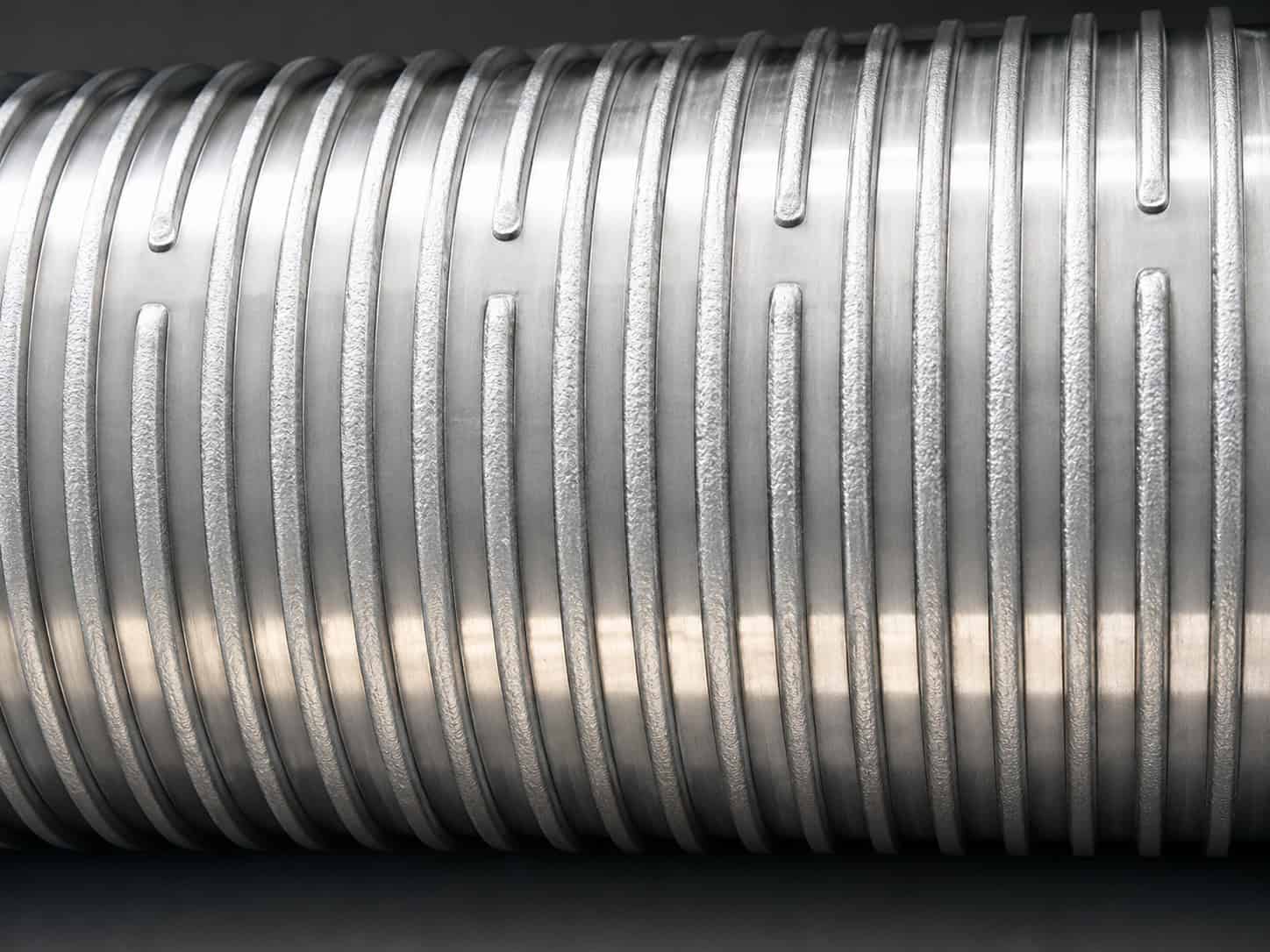
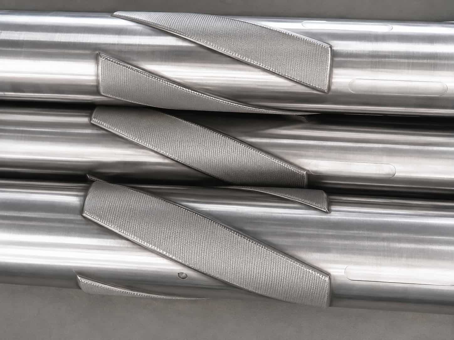
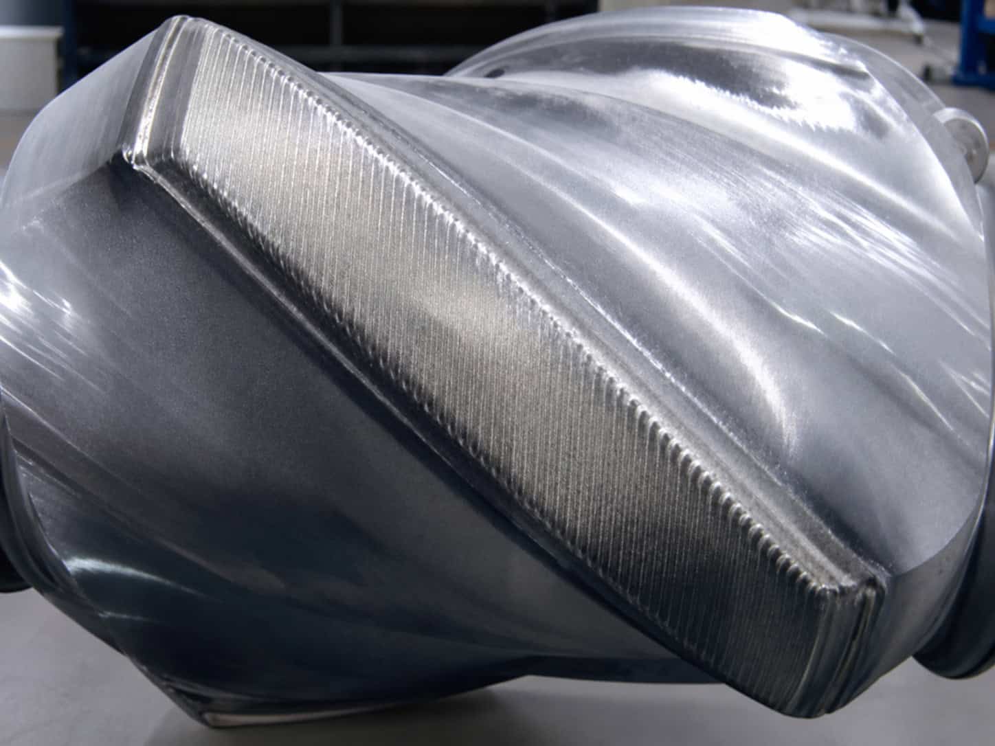
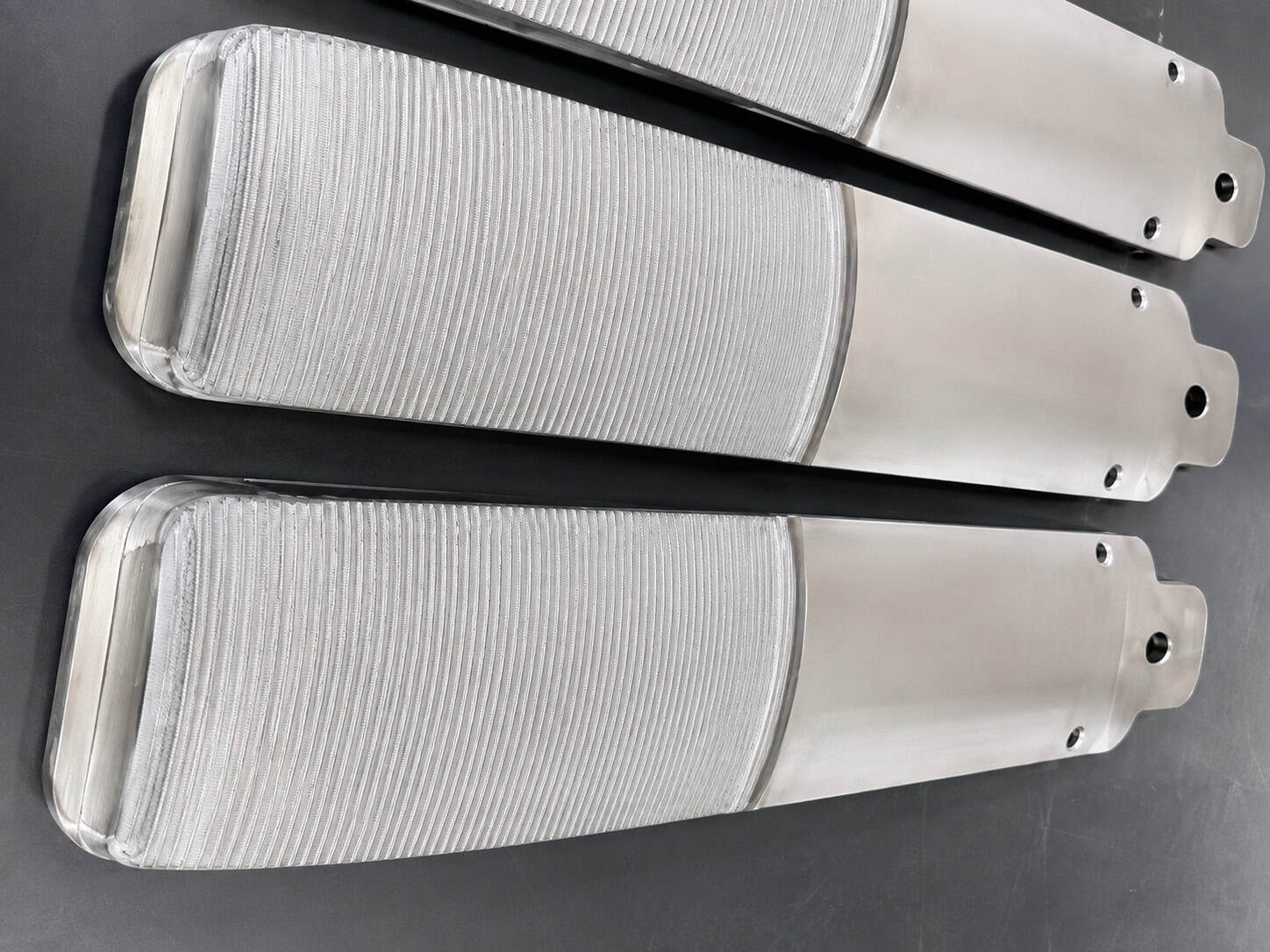
The actual application uses laser cladding to create wear-resistant bands or functional surfaces on the stabilizer body.
The engineering objective is to protect the high-wear regions while retaining the structural properties of the original component.
4. Why Localized Cladding Is Important for Stabilizers
A drilling stabilizer does not necessarily require the complete external surface to be covered.
Instead, laser cladding can selectively reinforce:
Wear Bands / Blades / Contact Regions / High-Wear Zones
This provides several advantages:
- Reduced alloy consumption
- Reduced processing time
- Lower unnecessary heat input
- Greater control of final dimensions
- Functional material only where required
This follows a fundamental surface-engineering principle:
Apply the high-performance material where the failure actually occurs.
5. Stabilizer Processing Strategy
Because stabilizers are predominantly cylindrical but contain raised blades or wear bands, the process requires coordinated motion.
Depending on stabilizer geometry, the system can use:
Workpiece Rotation + Axial Motion
or:
Multi-Axis CNC / Robot + Positioner
For simple circumferential wear bands:
Rotation + Controlled Laser Position = Circumferential Cladding
For helical or complex stabilizer surfaces:
Multi-Axis Coordinated Motion = Geometry-Following Cladding
This is why stabilizer projects must be evaluated from the actual drawing or 3D model.
6. Drill Pipe Wear-Band Laser Cladding
Drill pipes experience repeated contact and friction during drilling.
Wear-resistant bands can be deposited onto selected external regions to reduce wear of the underlying structural material.
A representative processing strategy is:
Surface Preparation
↓
Workpiece Positioning
↓
Rotary Laser Cladding
↓
Multi-Track Deposition
↓
Controlled Cooling
↓
Machining / Grinding if Required
↓
Final Inspection
Laser cladding provides a metallurgically bonded functional surface while allowing localized material deposition.
7. Drill Collar Laser Cladding
Drill collars operate under substantial mechanical loading and can experience wear on external contact surfaces.
Laser cladding can be applied to selected working regions to provide:
- Wear resistance
- Surface restoration
- Localized dimensional buildup
- Corrosion protection where required
Because drill collars can be long and heavy, equipment design must consider not only laser parameters but also:
- Workpiece weight
- Diameter
- Length
- Rotational stability
- Support
- Loading and unloading
8. Centralizer Laser Cladding
Centralizers contain functional surfaces that can experience continuous sliding and contact with surrounding structures.
The primary degradation mechanism is often concentrated on the outer contact regions.
Localized laser cladding allows these surfaces to be reinforced without unnecessarily processing the complete component.
Depending on geometry, processing can use:
- Rotary CNC
- Multi-axis CNC
- Robot + positioner
9. Sucker Rod Laser Cladding
Sucker rods operate continuously in oil-production systems and can be exposed to combinations of:
- Sliding wear
- Corrosion
- Contact damage
- Repeated mechanical loading
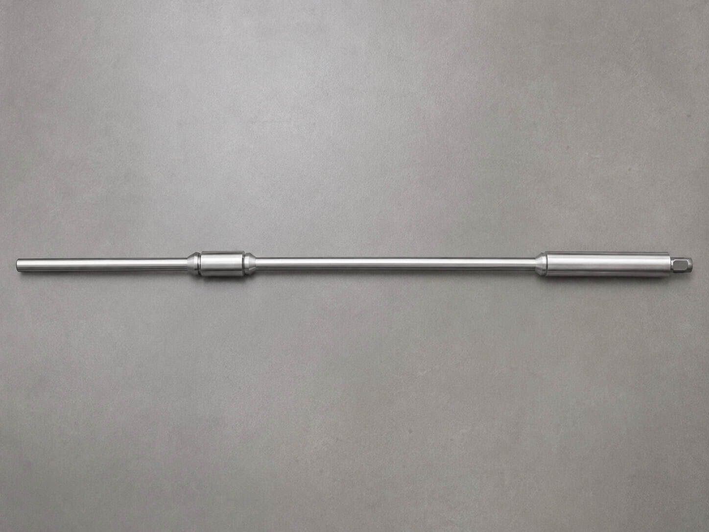
Laser cladding can be evaluated for localized surface enhancement or restoration of suitable high-value rod components.
Material selection should consider both mechanical wear and the actual production fluid.
10. Plunger Laser Cladding
Plungers require good dimensional accuracy and surface performance because their functional surfaces interact with sealing and pumping systems.
Common degradation can include:
- Abrasive wear
- Corrosion
- Surface scoring
- Dimensional loss
Laser cladding can restore material to the worn surface before final machining.
The process route becomes:
Worn Plunger
↓
Damage Removal
↓
Laser Cladding Buildup
↓
Final Grinding / Machining
↓
Restored Functional Dimension
This makes laser cladding particularly suitable for high-value plungers where the structural body remains serviceable.
11. Screw and Cylindrical Oilfield Components
Screw-type components can experience severe wear on their working surfaces.
Their helical geometry requires more complex synchronized motion than a simple shaft.
Depending on geometry, the system can coordinate:
Rotation + Axial Feed + Additional CNC Axis
to maintain:
- Correct stand-off distance
- Stable powder focus
- Appropriate track overlap
- Consistent layer geometry
Complex screws may require multi-axis or robotic processing.
12. TC Bearing and Wear Components
Oilfield bearing and wear components may require localized surface properties including:
- Abrasion resistance
- Erosion resistance
- High contact-wear resistance
- Dimensional stability
Laser cladding allows functional material to be deposited selectively onto the working surface.
The exact alloy system must be developed according to the original component material and wear mechanism.
13. New Component Surface Enhancement
Laser cladding is not limited to repair.
For new petroleum machinery components, the process can be incorporated into manufacturing:
Structural Component Manufacturing
↓
Functional Surface Preparation
↓
Laser Cladding
↓
Final Machining
↓
Quality Inspection
This creates a component consisting of:
Structural Base Material + High-Performance Functional Surface
The expensive wear-resistant material is concentrated only where required.
14. Oilfield Component Remanufacturing
For worn high-value components, laser cladding can also serve as a remanufacturing process.
The basic concept is:
Worn Component
↓
Failure Evaluation
↓
Removal of Damaged Material
↓
Laser Material Buildup
↓
Functional Surface Reconstruction
↓
Final Machining
↓
Return to Required Dimensions
This is particularly attractive when surface degradation occurs while the main structural body remains usable.
15. Metallurgical Bonding
Laser cladding creates a fusion interface between the deposited alloy and the substrate.
A controlled amount of substrate material is melted together with the deposited powder.
After solidification, the coating becomes metallurgically bonded to the component.
This is important for petroleum machinery because wear-resistant surfaces can experience substantial mechanical loading.
The process objective is:
Strong Metallurgical Bonding + Controlled Dilution + Dense Functional Layer
16. Why Dilution Control Matters
Excessive substrate melting can alter the chemistry of the deposited alloy.
This may reduce:
- Hardness
- Wear resistance
- Corrosion resistance
- Functional alloy performance
Therefore, laser power should not be considered independently.
The actual process window is determined by:
Laser Power + Powder Feed Rate + Spot Size + Travel Speed + Substrate + Layer Thickness
The objective is sufficient fusion without unnecessary substrate dilution.
17. Coating Material Selection
The original petroleum machinery case confirms laser cladding of wear-resistant surfaces but does not disclose a specific universal powder composition for the drilling components.
Therefore, the material must be selected according to each application.
Potential engineering families can include:
Iron-Based Alloys
Suitable for cost-effective wear-resistant surface enhancement in appropriate applications.
Nickel-Based Alloys
Suitable where wear resistance must be combined with stronger corrosion or temperature performance.
Metal-Matrix Composite Systems
Hard-particle-reinforced systems can be evaluated for severe abrasive wear applications.
However, hard-particle content must be balanced against:
- Toughness
- Crack sensitivity
- Machinability
- Impact resistance
There is no universal “best powder” for all petroleum machinery.
18. Process Parameters Required for Petroleum Components
The actual source case does not disclose numerical laser power, powder-feed rate, travel speed, hardness, dilution or layer thickness for the drilling components.
These parameters must therefore be developed for each project.
| Parameter | Engineering Function |
|---|---|
| Laser Power | Controls available melting energy |
| Spot / Track Width | Determines processing width and energy density |
| Powder Feed Rate | Controls deposition volume |
| Travel Speed | Influences heat input and productivity |
| Rotation Speed | Controls circumferential/helical deposition |
| Track Pitch | Controls overlap |
| Layer Thickness | Determines functional buildup |
| Number of Layers | Determines restoration amount |
| Shielding Gas | Protects powder stream and melt pool |
| Stand-Off Distance | Controls powder/laser convergence |
| Preheating | Evaluated according to substrate and alloy |
| Interpass Temperature | Controls thermal accumulation |
| Cooling Strategy | Manages workpiece temperature |
These parameters form an integrated:
Laser–Powder–Material–Motion–Thermal Process Window
19. Coating Thickness
Required thickness depends strongly on whether the objective is:
Surface Enhancement
Only enough functional material is deposited to provide the required surface properties.
Wear-Band Manufacturing
Thickness is designed according to the required wear allowance.
Remanufacturing
The deposited thickness must compensate for:
Existing Material Loss + Required Final Geometry + Machining Allowance
Therefore, a single coating-thickness value should not be applied to every petroleum component.
20. Final Machining
Many petroleum machinery components require accurate final dimensions.
Laser cladding can therefore be followed by:
- Turning
- Grinding
- Milling
- Polishing
The deposited layer must include appropriate machining allowance.
For plungers, shafts and wear bands, final surface finish may be just as important as the cladding process itself.
21. Quality Control
Depending on component criticality, inspection can include:
- Visual inspection
- Dimensional measurement
- Coating thickness
- Hardness testing
- Metallographic examination
- Dilution evaluation
- Porosity evaluation
- Crack inspection
- Bonding assessment
- Surface finish measurement
For corrosion-critical components, material chemistry and corrosion performance may require additional validation.
22. Automated Equipment Architecture
A representative petroleum machinery laser cladding system can include:
Industrial Fiber Laser
Powder Feeding System
Laser Cladding Head
Heavy-Duty Rotary Positioner
Long-Travel Linear Axis
Multi-Axis CNC / Robot if Required
Workpiece Support
Integrated Process Control
Cooling / Extraction / Safety System
The final machine configuration should follow the workpiece geometry.
23. Heavy-Duty Rotary System
Long petroleum components can place substantial mechanical demands on the machine.
Equipment design must evaluate:
- Maximum diameter
- Maximum length
- Maximum weight
- Center of gravity
- Rotational speed
- Support spacing
- Workpiece deflection
- Loading method
A technically correct laser process is insufficient if the workpiece cannot be rotated and supported accurately.
24. Robot + Positioner for Complex Oilfield Components
For components such as complex stabilizers or irregular wear surfaces, a robot and positioner can provide additional processing freedom.
The architecture becomes:
Robot Motion + Workpiece Rotation + Laser Cladding Process
This allows the laser head to maintain a more appropriate orientation relative to complex surfaces.
For repetitive production, validated robot paths can be stored and reused.
25. Bimetallic Clad Pipe as a Related Oil & Gas Application
The same broader laser surface-engineering technology is also used for corrosion-resistant bimetallic metallurgical clad pipes.
In the related real industrial application, the pipe structure consisted of:
Carbon Steel Structural Pipe
Corrosion-Resistant Internal Laser-Cladded Layer
Actual corrosion-resistant materials included:
- Stainless Steel 316
- Nickel Alloy 625
- Nickel Alloy 825
The related internal-wall system used:
6000 W laser power
while external/rapid cladding platforms included:
6000 W / 9000 W / 12000 W
This should be treated as a separate pipeline application rather than as the material specification for drilling stabilizers or drill pipes.
On the website, this section should internally link to the dedicated Bimetallic Metallurgical Clad Pipe Laser Cladding case instead of repeating the complete pipe article.
26. Laser Cladding vs. Conventional Hardfacing
Conventional arc hardfacing remains widely used in oilfield applications and can be economically attractive for large, heavy wear surfaces.
Laser cladding becomes particularly valuable where the application requires:
- Lower heat input
- Lower dilution
- Greater deposition precision
- Controlled dimensional buildup
- Localized reinforcement
- Automated repeatability
Neither process is universally superior.
For large, cost-sensitive surfaces with generous heat-input tolerance, conventional hardfacing or PTA may remain appropriate.
For high-value components requiring controlled deposition and precision, laser cladding can provide significant advantages.
27. Why Automation Matters
Petroleum machinery often includes repetitive cylindrical or rotational components.
Once the process is validated, automation allows consistent control of:
- Rotation
- Travel speed
- Track spacing
- Powder feed
- Layer thickness
- Processing position
For production quantities of similar stabilizers, drill collars, rods or plungers, this can transform laser cladding from manual repair into a repeatable industrial manufacturing process.
28. Actual Technical Data Summary
The information directly supported by the real industrial application is summarized below.
| Technical Item | Actual Application Information |
|---|---|
| Industry | Petroleum / Oilfield Machinery |
| Process | Laser Cladding |
| Main Application | Wear-Resistant Surface Enhancement & Repair |
| Drilling Component | Drilling Stabilizer |
| Other Components | Drill Pipe / Drill Collar / Centralizer / Sucker Rod / TC Bearing / Screw / Plunger |
| Functional Region | Wear Bands and Other High-Wear Surfaces |
| Main Failure Conditions | Wear / Corrosion / Abrasion / Complex Mechanical Loading |
| Main Objective | Wear & Corrosion Resistance / Service-Life Extension |
| Bonding Mechanism | Metallurgical Bonding |
| Processing Mode | Automated Powder-Fed Laser Cladding according to component geometry |
| Laser Power – Drilling Components | Project-specific; not disclosed in original case |
| Powder Material – Drilling Components | Project-specific; exact formulation not disclosed |
| Coating Thickness | Project-specific; not disclosed |
| Hardness | Project-specific; not disclosed |
| Powder Feed Rate | Project-specific; not disclosed |
| Travel Speed | Project-specific; not disclosed |
| Dilution | Process-controlled; numerical value not disclosed |
Related Bimetallic Pipe Application Data
| Parameter | Actual Data |
|---|---|
| Inner-Wall Laser Power | 6000 W |
| External/Rapid Cladding Platforms | 6000 / 9000 / 12000 W |
| Corrosion-Resistant Materials | 316 / Alloy 625 / Alloy 825 |
| Structural Pipe | Carbon Steel |
This separation is important because the pipeline parameters must not be represented as drilling-tool parameters.
29. Engineering Information Required for a Similar Project
For a petroleum machinery laser cladding project, GREENSTONE would normally require:
- Workpiece drawing / 3D model
- Component type
- Base material
- Diameter
- Length
- Weight
- Wear or damaged region
- Existing wear depth
- Required cladding area
- Required final dimensions
- Operating medium
- Corrosion conditions
- Abrasive conditions
- Required surface hardness/properties
- Required machining allowance
- Production quantity
For drilling stabilizers, it is especially important to provide the blade/wear-band geometry and exact region requiring cladding.
30. From Oilfield Component Repair to Complete Surface Engineering
A petroleum machinery laser cladding project should follow:
Failure Mechanism Analysis
↓
Base Material Identification
↓
Functional Alloy Selection
↓
Cladding Area Definition
↓
Laser Process Development
↓
Motion & Fixture Design
↓
Automated Deposition
↓
Final Machining
↓
Quality Validation
A drill pipe, stabilizer, sucker rod and plunger may all belong to the petroleum industry, but their surface requirements are fundamentally different.
GREENSTONE therefore develops the solution around the actual component, failure mechanism and operating environment, integrating laser cladding, powder delivery, motion systems, fixtures and automation into a customized oilfield surface-engineering solution.
Confidentiality Notice
This application case is based on actual industrial laser cladding applications for petroleum and oilfield machinery. The component categories, drilling stabilizer application, wear-band processing concept and associated industrial process information presented here are derived from actual applications. Customer identities, proprietary drawings, undisclosed alloy formulations, numerical process parameters and commercial information remain confidential. Representative images may be used where original project images cannot be published.
Have a Similar Petroleum Machinery Application?
Whether your project involves a drilling stabilizer, drill pipe, drill collar, centralizer, sucker rod, plunger, screw, bearing component or other oilfield wear part, process development should begin with the actual component and failure mechanism.
Send us your workpiece drawing, base material, dimensions, weight, wear condition, operating medium, required cladding area, target surface properties, machining requirements and production quantity. GREENSTONE’s engineering team can evaluate the appropriate cladding material, laser process and automated equipment architecture for your application.
