
Laser Cladding for Injection Molding Screws and Barrels: Wear-Resistant Repair and Bimetallic Barrel Manufacturing
Application Overview
Screws and barrels are core working components in plastic extrusion and injection molding equipment. During continuous production, the screw flights, flight edges, roots and barrel inner walls are exposed to combinations of:
- High-speed friction
- Abrasive fillers
- Chemical corrosion
- Elevated temperature
- Repeated mechanical loading
- Adhesive wear
Progressive wear increases the clearance between the screw and barrel, reducing plasticizing efficiency, pressure stability and dimensional consistency of the final product.
In this industrial application, laser cladding was used for both:
Screw Surface Repair and Reinforcement
and
Bimetallic Barrel Inner-Wall Manufacturing
The main engineering objectives were:
Wear Resistance + Corrosion Resistance + Dimensional Restoration + Reduced Material Adhesion + Extended Service Life
The actual application included both external screw laser cladding and internal barrel laser cladding.
1. Components Covered by This Application
The actual application included two main component groups:
Injection / Extrusion Screws
Typical processing regions include:
- Screw flights
- Flight edges
- Screw roots
- Localized worn surfaces
- Functional contact areas
Barrels
Main processing area:
- Internal cylindrical wall
For new bimetallic barrel manufacturing, the inner wall was built with a:
2–5 mm wear-resistant, corrosion-resistant and high-temperature-resistant alloy layer.
This is one of the key real technical parameters of the application.
2. Why Screws and Barrels Wear
Injection molding and extrusion screws operate continuously against polymer materials under substantial pressure and temperature.
Wear becomes more severe when processing plastics containing:
- Glass fiber
- Mineral fillers
- Flame-retardant additives
- Engineering plastics
- Abrasive reinforcing particles
Special plastics can further increase both wear and corrosion.
The original application specifically identifies processing environments involving materials such as:
- Engineering plastics
- Fluoroplastics
- Polysulfone
- PPO
- Other special plastic materials
Under these conditions, the working surfaces of conventional screws and barrels may deteriorate relatively quickly.
3. Typical Screw Failure Mechanisms
Screw degradation can appear on several different regions.
Flight Edge Wear
The outer edge of the screw flight experiences continuous sliding and abrasive contact.
Loss of flight height increases the clearance between screw and barrel.
Flight Surface Wear
Broad working surfaces can develop:
- Abrasion
- Grooving
- Surface roughening
- Localized dimensional loss
Chemical Corrosion
Certain polymers, additives and processing environments can attack the metal surface.
Adhesive Wear
Polymer or process material can adhere to the working surface and contribute to unstable friction and material transport.
These effects can reduce:
- Plasticizing efficiency
- Output stability
- Product quality
- Equipment efficiency
4. Why Laser Cladding Was Selected
Laser cladding provides a useful combination of surface reinforcement and dimensional rebuilding.
For screws and barrels, its advantages include:
- Metallurgical bonding
- Localized heat input
- Controlled material buildup
- Low dilution compared with many conventional fusion processes
- Precision repair of worn regions
- Wear-resistant alloy deposition
- Corrosion-resistant alloy deposition
- Automated processing
- Compatibility with final machining
The process allows a relatively inexpensive structural body to be combined with a higher-performance functional surface.
5. Screw Laser Cladding
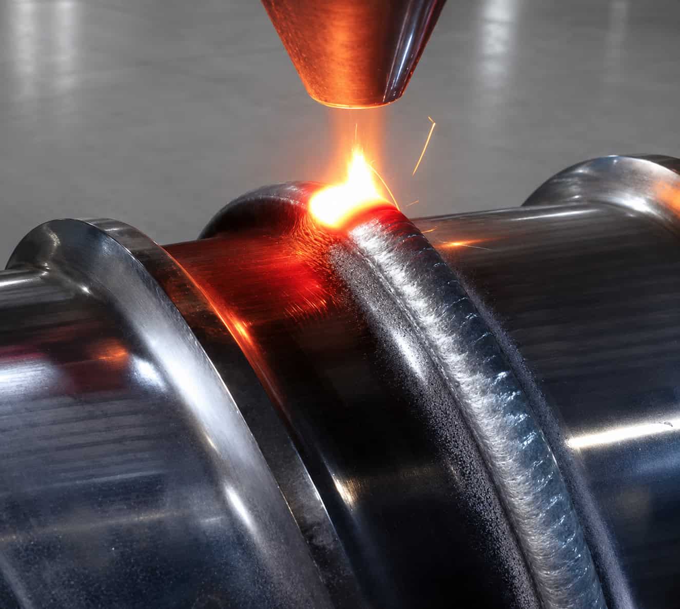
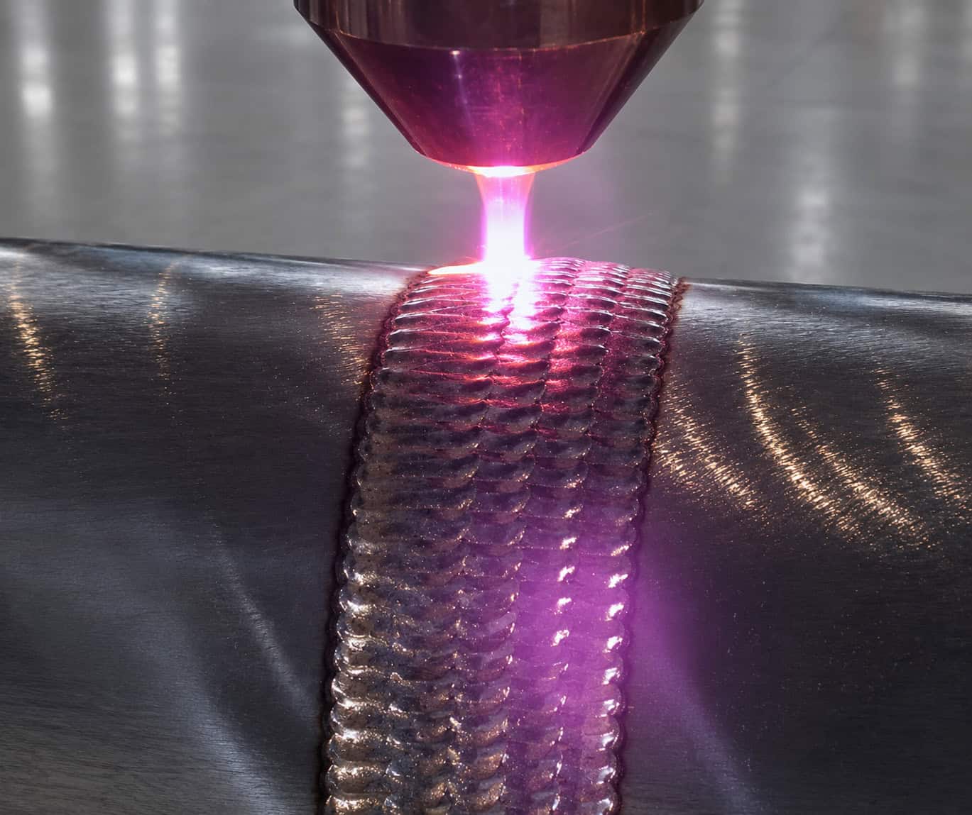
The actual application uses laser cladding on the screw flights and other wear-critical surfaces.
Unlike a simple cylindrical shaft, a screw contains a continuously changing helical geometry.
The cladding system must coordinate:
Workpiece Rotation + Axial Movement + Screw Pitch Geometry
The processing head follows the flight path while maintaining a stable relationship between:
- Laser position
- Powder focus
- Stand-off distance
- Travel speed
- Track overlap
This makes screw laser cladding primarily an automation and coordinated-motion problem, in addition to being a metallurgical deposition process.
6. Screw Flight Repair
For a worn screw, the basic repair objective is:
Restore Flight Geometry + Improve Future Wear Resistance
A representative repair sequence is:
Inspection
↓
Wear Measurement
↓
Removal of Defective Surface Material
↓
Surface Preparation
↓
Laser Cladding
↓
Controlled Cooling
↓
Machining / Grinding
↓
Final Dimensional Inspection
The deposited material is normally applied with sufficient allowance for final machining.
7. Screw Surface Reinforcement for New Components
Laser cladding can also be used during new screw manufacturing.
Instead of waiting for the screw to wear, a functional coating can be deposited directly onto high-wear regions during production.
The concept becomes:
Structural Screw Body
Localized Wear-Resistant Laser-Clad Surface
This can reduce the need to manufacture the entire screw from a more expensive high-alloy material.
8. Material Strategy for Screw Laser Cladding
The original application specifically identifies the use of high-hardness wear-resistant and corrosion-resistant alloy coatings.
Depending on the application, material systems can include:
- Tungsten-carbide-containing alloys
- Nickel-based alloys
- Cobalt-based alloys
- Stellite-type alloys
- Other wear-resistant metallic systems
The correct material depends on:
- Polymer type
- Filler content
- Operating temperature
- Wear mechanism
- Corrosive environment
- Required machining properties
A screw processing glass-fiber-filled engineering plastics may require a different material strategy from one processing less abrasive conventional polymers.
9. Tungsten Carbide Reinforcement
Tungsten carbide can be incorporated into a metallic matrix where severe abrasive wear is the dominant problem.
The hard carbide phase improves resistance to abrasion while the metallic matrix provides:
- Bonding
- Toughness
- Support for hard particles
However, maximum carbide content is not automatically desirable.
Excessive hard-phase content can increase:
- Brittleness
- Crack sensitivity
- Machining difficulty
Therefore, tungsten carbide content must be optimized according to the actual screw and service conditions.
10. Nickel-Based Alloy Systems
Nickel-based alloys are suitable where the working surface requires a combination of:
- Wear resistance
- Corrosion resistance
- High-temperature stability
- Metallurgical compatibility
They can also serve as the metallic matrix for carbide-reinforced coatings.
For aggressive plastics-processing environments, this balance can be more useful than hardness alone.
11. Cobalt-Based and Stellite-Type Alloys
The original application also identifies cobalt-based and Stellite-type materials.
These systems can provide combinations of:
- Wear resistance
- Elevated-temperature performance
- Corrosion resistance
- Friction resistance
However, their higher material cost means they should be selected where their performance is technically justified.
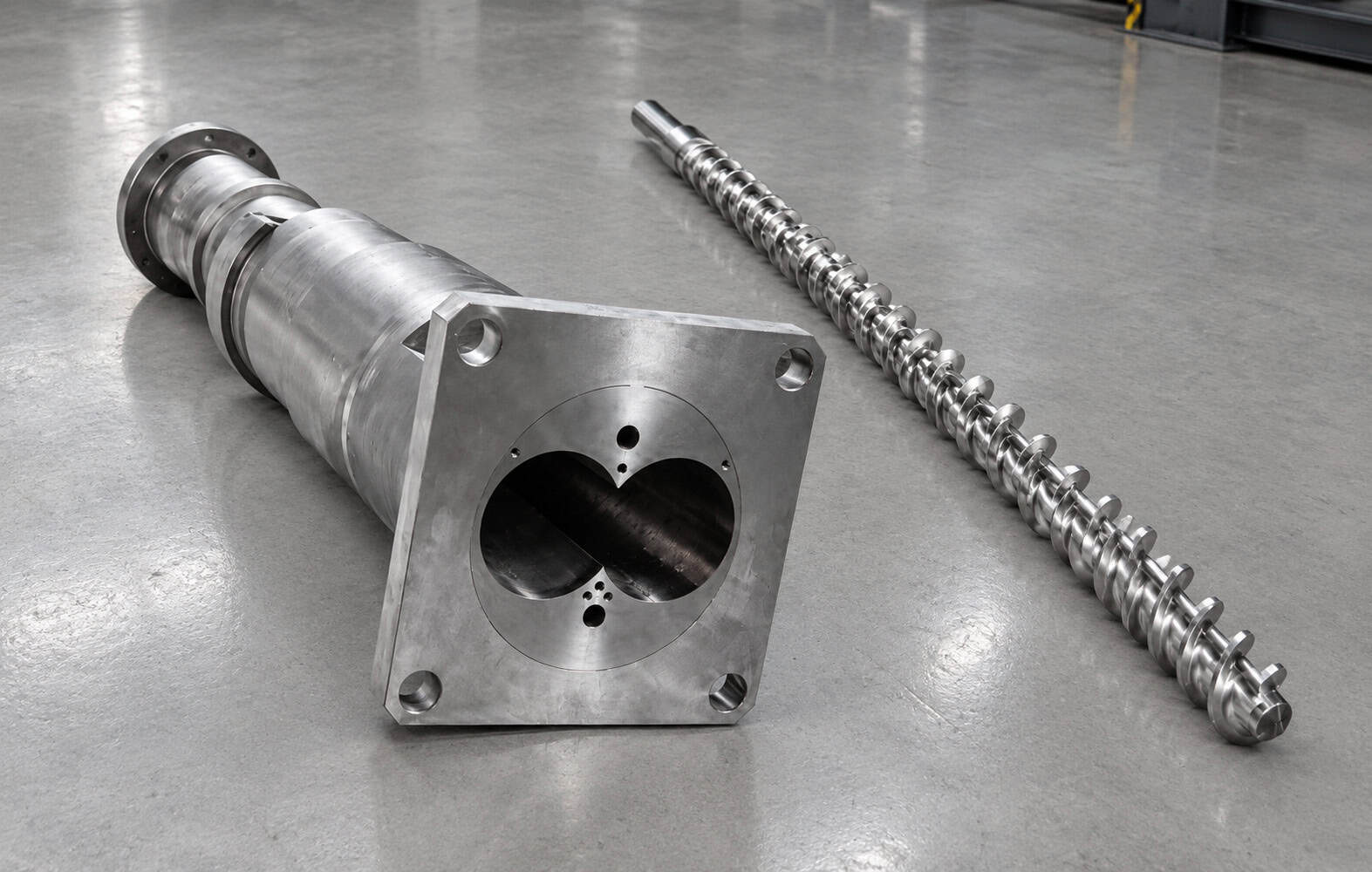
12. Bimetallic Barrel Manufacturing
In addition to screw surface reinforcement, the actual industrial application included bimetallic barrel manufacturing.
The barrel uses a structural body combined with a high-performance alloy inner wall.
The real application specifies an internal functional layer thickness of:
2–5 mm
This layer is cast or deposited onto the barrel inner wall to provide:
- Wear resistance
- Corrosion resistance
- High-temperature resistance
The bimetallic structure allows the bulk barrel to retain its structural function while concentrating expensive high-performance material only on the inner working surface.
13. Actual Bimetallic Barrel Material Systems
The original application lists the following functional inner-wall materials:
- Tungsten Carbide Alloy
- Nickel-Based Alloy
- Cobalt-Based Alloy
- Stellite Alloy
These materials are selected according to the type of plastic being processed and the required wear/corrosion performance.
14. Why a 2–5 mm Inner Layer Is Important
The real application uses:
2–5 mm functional alloy thickness
rather than an extremely thin surface coating.
This provides enough material to support:
- Long-term wear allowance
- Corrosion protection
- Final machining
- Functional inner-wall geometry
The barrel therefore differs from HVOF or PVD applications where the coating is primarily a thin functional surface.
This is a true material buildup and bimetallic surface-engineering application.
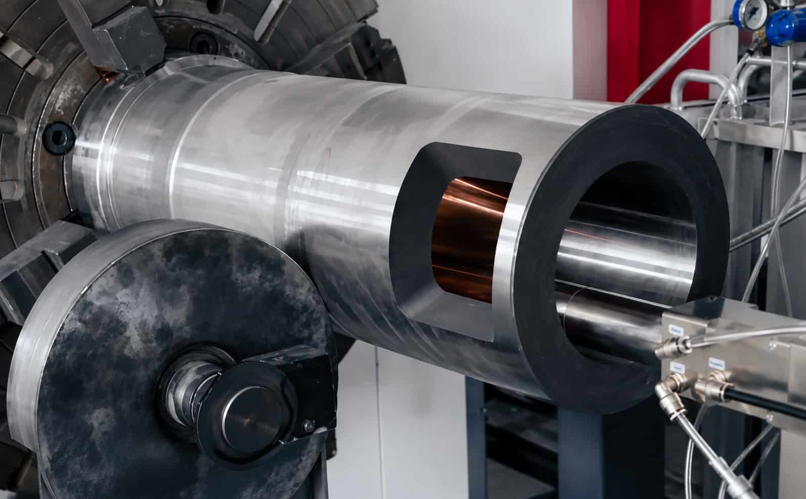
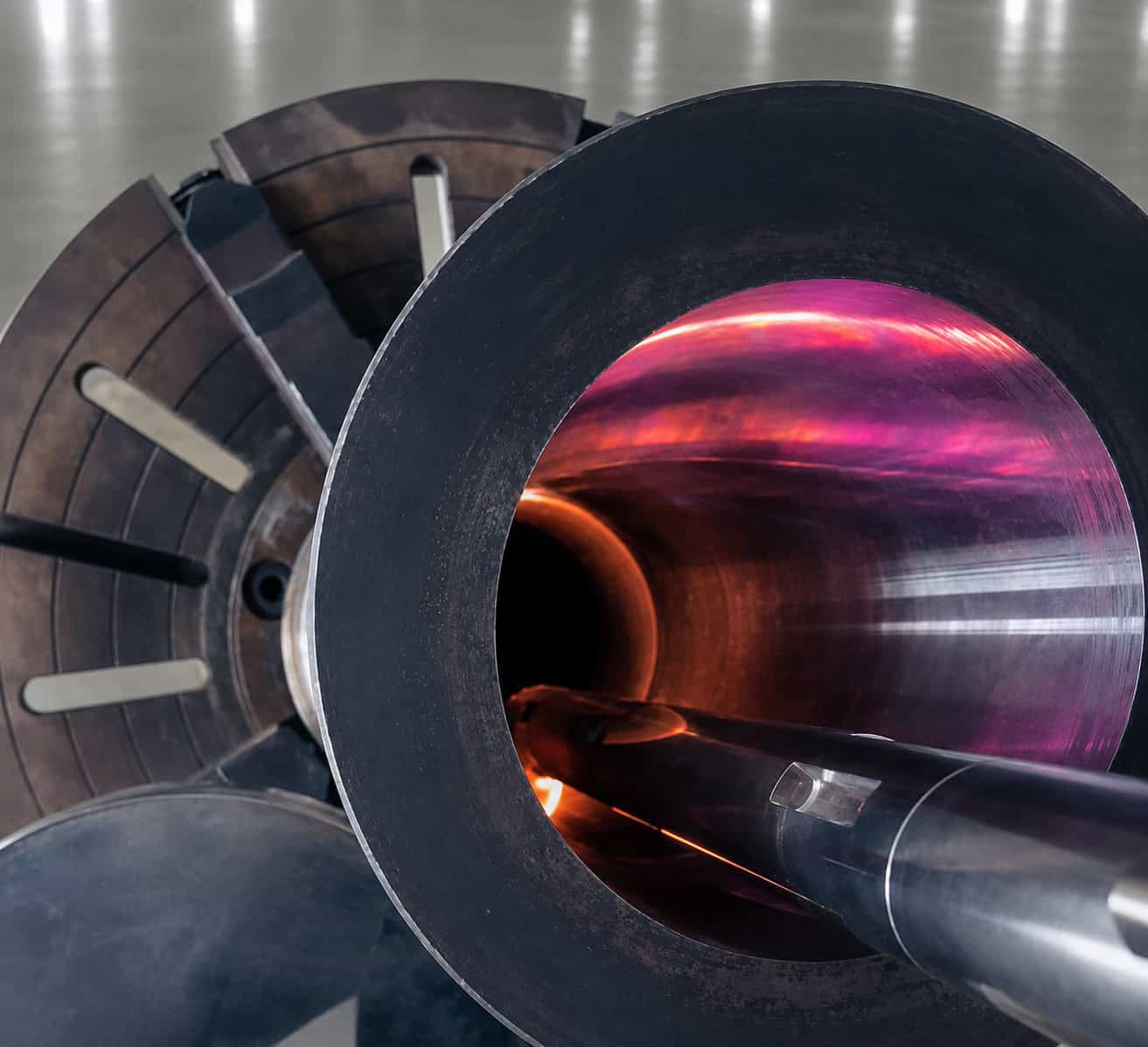
15. Barrel Inner-Wall Laser Cladding
Internal barrel processing is technically more challenging than screw external cladding.
The laser head must enter the barrel bore while maintaining stable:
- Laser delivery
- Powder delivery
- Shielding gas
- Stand-off distance
- Focal position
- Melt-pool geometry
- Cooling
A dedicated internal-diameter laser cladding system is therefore required.
The process principle can be:
Barrel Rotation + Internal Cladding Head Axial Movement
or another synchronized architecture depending on the machine design.
16. Inner-Wall Processing Challenges
Important engineering constraints include:
- Minimum barrel internal diameter
- Barrel length
- Internal processing depth
- Head insertion distance
- Mechanical deflection
- Powder delivery stability
- Heat accumulation
- Internal gas flow
- Collision avoidance
- Cladding-head cooling
For long barrels, equipment stiffness and support architecture become as important as laser power.
17. Actual Laser Power Configurations
The original industrial application provides clear laser power information.
Outer-Wall / Rapid Laser Cladding Equipment
Actual available power configurations:
- 6000 W
- 9000 W
- 12000 W
Inner-Wall Laser Cladding Equipment
Actual configuration:
- 6000 W
These power levels support different screw, barrel and related external/internal cladding requirements.
18. Actual Technical Data
| Technical Item | Actual Application Data |
|---|---|
| Application | Injection / Extrusion Screw and Barrel |
| Process | Powder-Fed Laser Cladding |
| Bimetallic Barrel Layer Thickness | 2–5 mm |
| Outer / Rapid Cladding Laser Power | 6000 / 9000 / 12000 W |
| Inner-Wall Laser Power | 6000 W |
| Functional Materials | WC Alloy / Ni-Based / Co-Based / Stellite |
| Screw Processing | Helical External Surface |
| Barrel Processing | Internal Cylindrical Surface |
| Main Objectives | Wear / Corrosion / High-Temperature Resistance |
| Component Type | New Manufacturing + Repair / Reinforcement |
These values are directly supported by the real industrial application.
19. Why Different Laser Powers Are Used
Laser power should be matched to:
- Material
- Layer thickness
- Powder-feed rate
- Travel speed
- Beam geometry
- Required deposition rate
- Workpiece thermal mass
Higher power systems can provide more processing capacity for:
- Higher deposition rates
- Wider tracks
- Faster production
- Larger components
However:
More Laser Power ≠ Automatically Better Cladding
The process must remain balanced between:
Laser Power + Powder Feed + Travel Speed + Track Width + Material + Heat Input
20. Actual Motion-System Architectures
The original application lists several motion-system configurations.
Four-Axis Laser Cladding Machine
Suitable for coordinated screw and cylindrical processing.
Robot + Slide + Large Rotary Table
Suitable for larger parts and more complex processing paths.
Robot + Positioner
Provides coordinated multi-axis movement.
Gantry-Type Large Motion System
Suitable for large working envelopes and heavy industrial components.
These architectures demonstrate that screw and barrel applications should not be forced into one standard machine format.
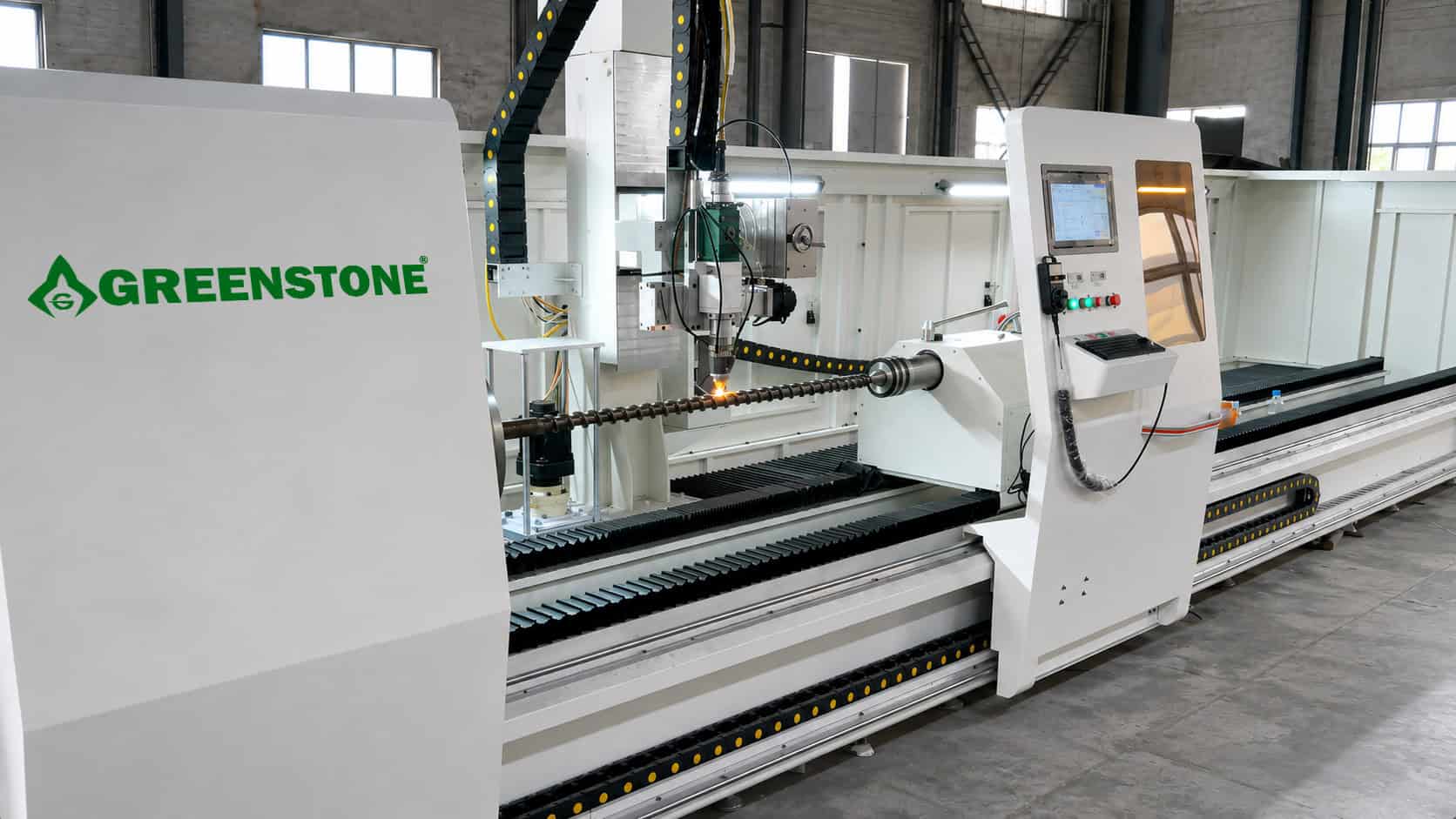
21. Four-Axis System for Screw Processing
A four-axis system is particularly suitable for helical screw geometry.
The coordinated axes can control:
- Workpiece rotation
- Axial movement
- Radial position
- Additional positioning / orientation
This allows the laser head to follow the screw flight more accurately than a simple two-axis cylindrical system.
For repetitive screw geometries, a CNC architecture can provide high stability and repeatability.
22. Robot + Positioner Architecture
For screws or related components with more complex geometries, a robot combined with a positioner can provide greater flexibility.
The coordinated system can control:
Robot Position + Workpiece Rotation + Laser Orientation
This is useful where the cladding head must maintain a changing angle or stand-off distance.
23. Process Parameters That Must Be Developed Per Project
The original application does not publish fixed numerical values for:
- Powder-feed rate
- Travel speed
- Screw rotational speed
- Track pitch
- Hardness
- Dilution
- Spot size
These must be developed according to the actual screw or barrel.
| Parameter | Engineering Function |
|---|---|
| Laser Power | Controls available energy |
| Powder Feed Rate | Controls material deposition |
| Travel Speed | Controls heat input and productivity |
| Screw Rotation | Controls helical deposition path |
| Track Pitch | Controls overlap |
| Spot Size | Controls energy density and track width |
| Layer Thickness | Controls repair / wear allowance |
| Number of Layers | Controls total buildup |
| Shielding Gas | Protects melt pool |
| Preheating | Evaluated according to substrate/material |
| Interpass Temperature | Controls thermal accumulation |
| Cooling | Maintains process stability |
The correct process is a complete:
Laser–Powder–Material–Motion–Thermal Window
24. Screw Geometry and Cladding Path Programming
One of the most important practical requirements is accurate mapping of:
- Screw pitch
- Flight height
- Flight width
- Root diameter
- Total length
- Cladding position
The machine path must follow these geometric features.
For variable-pitch screws, twin screws or other complex profiles, programming becomes significantly more demanding.
A drawing or 3D model should therefore be provided before system design.
25. Internal Barrel Processing Strategy
For barrel inner-wall cladding, the system must coordinate:
Internal Head Position + Barrel Rotation + Axial Feed
The goal is to maintain uniform:
- Layer thickness
- Track overlap
- Heat input
- Powder distribution
across the complete internal working surface.
Because the functional layer can reach 2–5 mm, multiple-pass or multi-layer deposition may be required depending on process design.
26. Multi-Layer Deposition
A 2–5 mm functional layer may require multiple layers depending on:
- Single-layer deposition thickness
- Alloy
- Laser power
- Dilution requirement
- Crack sensitivity
- Machining allowance
Multi-layer processing requires careful control of:
- Interpass temperature
- Track position
- Heat accumulation
- Layer-to-layer bonding
The objective is not simply to deposit the required thickness as quickly as possible.
27. Dimensional Restoration
For worn screws, laser cladding can rebuild material that has already been lost.
The final deposition amount must consider:
Wear Depth + Required Final Geometry + Machining Allowance
The repaired screw can subsequently undergo:
- Turning
- Grinding
- Milling
- Polishing
depending on the functional surface.
28. Surface Finish
Screw and barrel surfaces interact directly with polymer flow.
Therefore, final surface condition can affect:
- Material transport
- Adhesion
- Friction
- Processing stability
- Product quality
Laser cladding is therefore only one part of the complete manufacturing route.
Final machining and polishing may be essential.
29. Laser Cladding vs. Conventional Nitriding
Nitriding is widely used for screws and barrels and can provide an economical hardened surface.
However, it modifies the existing surface rather than adding a thick new functional alloy.
Laser cladding becomes particularly valuable when:
- The original surface has already lost material
- Greater buildup is required
- A different corrosion-resistant alloy is required
- Tungsten carbide reinforcement is needed
- Significant dimensional restoration is required
A simplified distinction is:
Surface Hardening Only → Nitriding
New Functional Material + Dimensional Buildup → Laser Cladding / Bimetallic Surface
30. Laser Cladding vs. Conventional Bimetallic Barrels
Conventional bimetallic barrels are already highly effective and mature industrial products.
Laser cladding should not be described as universally replacing conventional bimetallic manufacturing.
Its advantages become relevant where manufacturers require:
- Flexible alloy deposition
- Localized repair
- Controlled material buildup
- Customized internal surfaces
- Automated remanufacturing
- Selective restoration of worn barrels
The correct manufacturing route depends on production quantity, barrel size, alloy and economics.
31. New Manufacturing vs. Repair
This application supports two distinct business scenarios.
New Manufacturing
Structural Screw / Barrel
Wear-Resistant Functional Surface
Repair / Remanufacturing
Worn Screw / Barrel
Laser Material Buildup
Final Machining
Restored Component
The same laser deposition platform can therefore support both OEM production and remanufacturing.
32. Why Automation Is Important
Screws and barrels often have repetitive geometries and long processing lengths.
Automation allows consistent control of:
- Screw rotation
- Axial movement
- Track position
- Laser power
- Powder feeding
- Layer geometry
Once a process is validated, recipes can be reused for repeated part families.
This makes the technology suitable for production rather than only one-off repair.
33. Quality Control
Depending on the component and application, quality control may include:
- Visual inspection
- Dimensional inspection
- Layer thickness
- Hardness
- Metallography
- Porosity
- Crack inspection
- Dilution evaluation
- Bonding quality
- Surface roughness
- Final screw/barrel clearance
For barrels, final internal diameter and surface finish are especially important.
34. Recommended Equipment Architecture
A representative GREENSTONE screw-and-barrel laser cladding platform can integrate:
6–12 kW Industrial Fiber Laser
Powder Feeder
External Cladding Head
Internal-Diameter Cladding Head
Four-Axis CNC / Robot
Heavy-Duty Rotary System
Long-Travel Linear Axis
Integrated Process Control
Cooling / Shielding / Extraction / Safety
The final configuration should follow the actual production requirement.
35. Equipment Selection by Workpiece
For screw projects, GREENSTONE would evaluate:
- Screw diameter
- Screw length
- Screw pitch
- Flight geometry
- Weight
- Processing area
- Material
- Wear depth
For barrel projects:
- Outer diameter
- Inner diameter
- Barrel length
- Weight
- Internal processing depth
- Required 2–5 mm functional layer
- Alloy
- Final bore tolerance
The system should therefore be designed according to:
Geometry + Material + Layer Requirement + Production Volume
rather than laser power alone.
36. Technical Data Summary
| Item | Actual / Application Data |
|---|---|
| Industry | Plastic / Injection / Extrusion Machinery |
| Main Components | Screw + Barrel |
| Screw Process | External Helical Laser Cladding |
| Barrel Process | Internal-Wall Laser Cladding / Bimetallic Manufacturing |
| Functional Layer Thickness | 2–5 mm |
| Outer / Rapid Laser Power | 6000 / 9000 / 12000 W |
| Internal-Wall Laser Power | 6000 W |
| Materials | WC Alloy / Nickel-Based / Cobalt-Based / Stellite |
| Main Surface Functions | Wear / Corrosion / High-Temperature Resistance |
| Motion Options | 4-Axis / Robot + Slide + Large Rotary Table / Robot + Positioner / Gantry |
| Main Failure Areas | Flight Surface / Flight Edge / Barrel Inner Wall |
| Manufacturing Mode | New Component Enhancement + Repair / Remanufacturing |
| Powder Feed Rate | Project-specific; not disclosed |
| Processing Speed | Project-specific; not disclosed |
| Hardness | Project-specific; not disclosed |
| Dilution | Process-controlled; numerical value not disclosed |
| Post-Processing | Machining / Grinding / Polishing according to component |
37. From Screw Wear to a Complete Surface Engineering Solution
A successful screw-and-barrel laser cladding project should follow:
Polymer / Filler Analysis
↓
Failure Mechanism Analysis
↓
Base Material Identification
↓
Functional Alloy Selection
↓
Wear / Restoration Thickness Definition
↓
Laser Process Development
↓
Helical / Internal Motion Design
↓
Fixture and Support Design
↓
Automated Laser Cladding
↓
Final Machining
↓
Quality Validation
The important point is that the solution should be selected according to the material being processed and the actual component geometry.
A screw processing conventional polymers and one processing highly abrasive glass-fiber-filled engineering plastics should not automatically use the same surface material.
At GREENSTONE, screw and barrel projects can therefore be developed as complete wear-resistant surface engineering + precision laser cladding + automated remanufacturing systems.
Confidentiality Notice
This application case is based on actual industrial laser cladding applications for injection molding and extrusion screws and barrels. The 2–5 mm bimetallic barrel layer thickness, 6000/9000/12000 W external cladding platforms, 6000 W internal-wall system, tungsten-carbide, nickel-based, cobalt-based and Stellite material options, and listed motion architectures are derived from the actual application. Customer identities, proprietary drawings, undisclosed process parameters and commercial information remain confidential.
Have a Similar Screw or Barrel Application?
If your project involves an injection molding screw, extrusion screw, twin-screw component, screw flight, worn barrel or bimetallic barrel inner wall, system development should begin with the actual geometry and processed material.
Send us your workpiece drawing, base material, screw/barrel dimensions, pitch and flight geometry, wear depth, required 2–5 mm functional layer where applicable, polymer type, filler content, target surface properties and production quantity. GREENSTONE’s engineering team can evaluate the alloy system, laser process and appropriate automated equipment architecture for your application.
